Incremental position sensors, commonly known as incremental encoders, measure motion by detecting discrete steps of linear or angular displacement. Information about the actual position or angle is not detected, only the fact that a motion corresponding to a known discrete step has taken place. The steps are equally spaced within the physical motion envelope of the sensor. A microcontroller or other external circuitry is required to keep track of the detected increments in order to obtain information about actual position and speed. This is what mainly differentiates incremental encoders from absolute encoders, which can provide correct position data directly after start-up without the need for motion. Incremental encoders, on the other hand, need to be put to a known position when power is cycled in order to provide correct position data.
Due to its low cost, the incremental rotary encoder is widely used in many industries and applications, and it is available with resolutions ranging from a few counts to thousands of counts per revolution. Linear incremental encoders are also available.
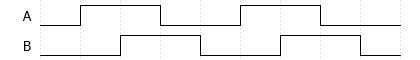
The simplest form of incremental encoders have a single output line on which a signal toggles to indicate each position increment. This signal does not provide information about the direction of movement. When direction sensing is required, a dual-channel quadrature encoded output is commonly used.
| Positive Direction | Negative Direction | ||
|---|---|---|---|
| A | B | A | B |
| 0 | 0 | 0 | 0 |
| 1 | 0 | 0 | 1 |
| 1 | 1 | 1 | 1 |
| 0 | 1 | 1 | 0 |

Many incremental encoders also provide an additional third signal called an index pulse or Z-pulse. This signal only goes high on one specific position in the motion envelope of the sensor, which means once per mechanical revolution for rotary encoders. This can be used as an accurate reference point for position calibration.