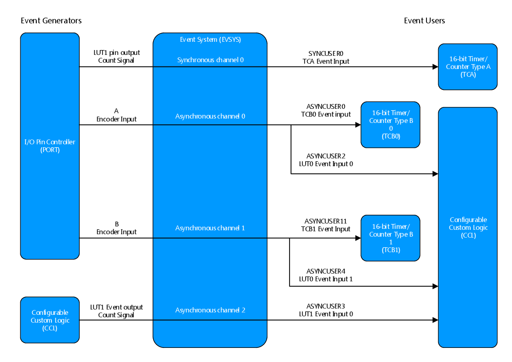
The two encoder inputs are each routed from the I/O Pin Controller (PORT) module to an asynchronous event channel. They are then passed on to the Configurable Custom Logic (CCL) and the two 16-bit Timer/Counter Type B (TCB) modules by configuring the event user registers to the correct event channels.
The output from LUT1 is used both as the event generator for asynchronous channel 2 directly, and as the generator for synchronous channel 0 indirectly via the pin. This is represented by the top and bottom arrows in the figure above. The reason is that the 16-bit Timer/Counter Type A (TCA) module accepts only synchronous events, while the Configurable Custom Logic (CCL) generates asynchronous events. Passing the asynchronous event via the I/O Pin Controller (PORT) module to generate synchronous events is, therefore, needed for this application.