A total of eight device pins are needed to realize the described setup. Four pins are configured as inputs, the other four as outputs. The figure below shows an example of specific pin allocation and their usage when implementing the application on an ATtiny1617 device. The accompanying code is written for the ATtiny1617, but with little effort, it can be ported to other devices that have the required peripherals.
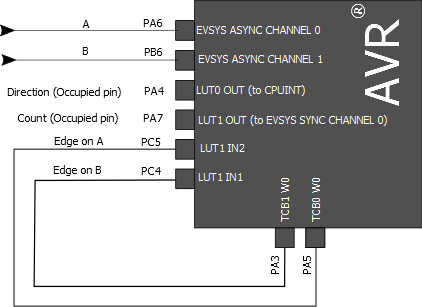
The two encoder inputs are connected to the fully asynchronous pins PA6 and PB6 for minimal input latency. The other two configured pin inputs, PC4 and PC5, which are used by LUT1 on the device, are physically connected to the output pins of the TCB modules, PA3 and PA5. This is to minimize the latency from the TCB modules to LUT1 by taking advantage of the asynchronous pin output of the TCB.
The last two utilized pins are the output pins of the two LUTs, PA4 and PA7. In order to update the 16-bit Timer/Counter Type A (TCA) count direction, PA4 is also configured to sense both edges of the signal on the pin and initiate execution of the PORTA ISR, which handles the actual direction update. PA7 is used as the event generator for synchronous channel 0 in the event system due to the need of routing the count signal to the 16-bit Timer/Counter Type A (TCA).