This application note focuses on the generation of two binary signals from the quadrature pulses created by an incremental encoder. One signal for counting incremental pulses and one for keeping track of counting direction. Many of the operations can be offloaded from the CPU using Core Independent Peripherals like the Configurable Custom Logic (CCL), Event System (EVSYS), and Timer/Counters. Since both the count signal and the direction signal can be generated from logic expressions that take the quadrature signals as inputs, the idea is to resolve these expressions using the Configurable Custom Logic (CCL) module. The two signals can then be passed via the event system to the 16-bit Timer/Counter Type A (TCA), which have the ability to count events. The counter value will be increased or decreased according to the count signal and the configured direction. The registers of the Timer/Counter hold the counter value and counting direction to be mapped to a physical position.
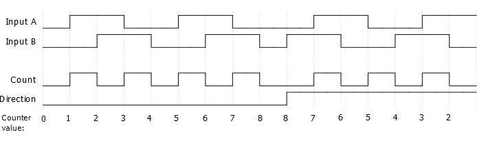
The count signal must indicate which of the two quadrature inputs contains the previous edge. It shall be low if the previous edge was on A, and high if it was on B. This gives a single increment or decrement of the counter value on each edge of the count signal. Any consecutive edge on the same channel indicates a direction change and must not produce an edge on the count signal. The edge detection is performed without CPU intervention by passing each input via the event system to a 16-bit Timer/Counter Type B (TCB) with dual event edge detection enabled.
The direction signal represents the physical direction of motion as indicated by the last edge on either of the two quadrature input signals.
The first figure below outlines the desired count signal, direction signal, and counter value, along with the input signals.
By moving as many operations as possible to the peripherals instead of executing them on the CPU, the available FLASH, SRAM, and CPU cycles are increased - leaving more headroom for implementing additional functionality. The figure below outlines how the peripherals and the flow of signals between them are set up.
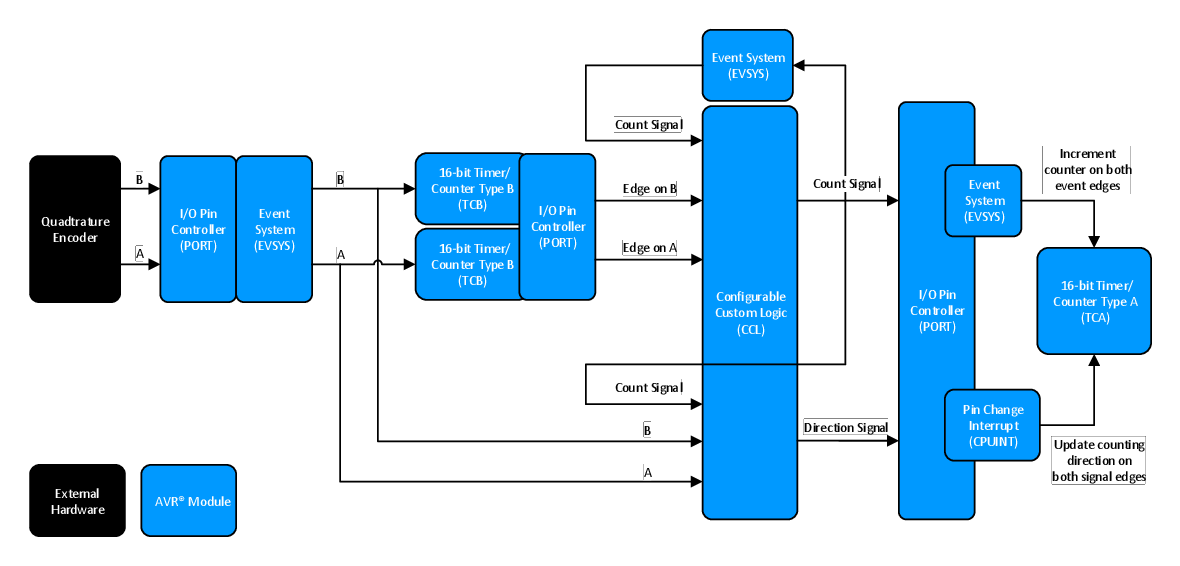
Since the single event input for the 16-bit Timer/Counter Type A (TCA) is used for counting incremental pulses, a pin change interrupt is used for updating the timer count direction.
Descriptions of how the different modules are configured are provided in the following sections.