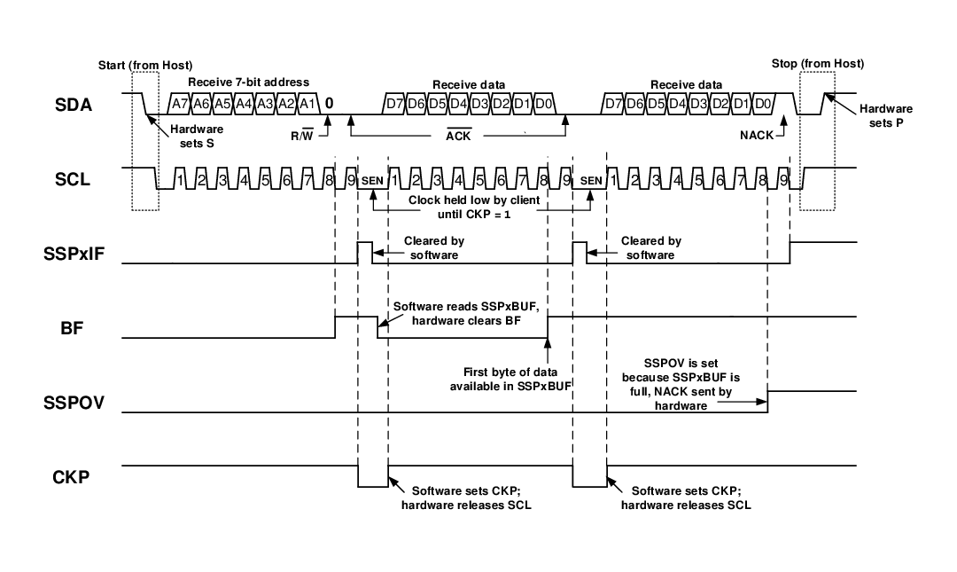
This section describes a standard sequence of events for the MSSP module configured as an I2C client in 7-bit Addressing mode. Figure 1 and Figure 2 are used as a visual reference for this description.
This is a step by step process of what typically must be done to accomplish I2C communication.
- 1.Start condition detected.
- 2.The Start (S) bit is set; SSPxIF is set if the Start Condition Interrupt Enable (SCIE) bit is set.
- 3.Matching address with WR/ bit clear is received.
- 4.The client pulls SDA low, sending an ACK to the host, and sets SSPxIF bit.
- 5.Software clears the SSPxIF bit.
- 6.Software reads received address from SSPxBUF, clearing the BF flag.
- 7.If SEN
=
1; Client software sets the CKP bit to release the SCL line. - 8.The host clocks out a data byte.
- 9.Client drives SDA low, sending an ACK to the host, and sets SSPxIF bit.
- 10.Software clears SSPxIF.
- 11.Software reads the received byte from SSPxBUF, clearing BF.
- 12.Steps 8-12 are repeated for all received bytes from the host.
- 13.Host sends Stop condition, setting the Stop (P) bit, and the bus goes Idle.
Figure 1. I2C
Client, 7-Bit Address, Reception (SEN =
0, AHEN = 0,
DHEN = 0)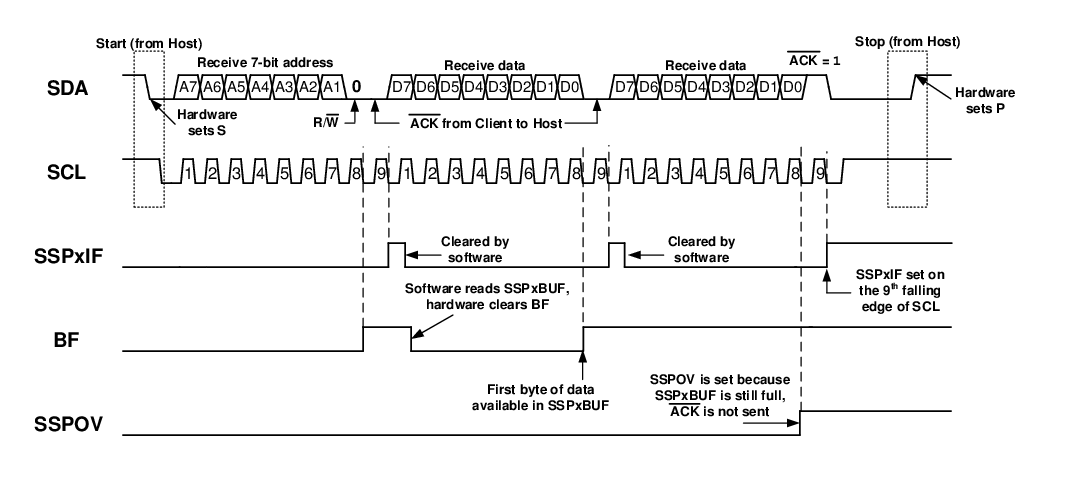
Figure 2. I2C
Client, 7-Bit Address, Reception (SEN =
1, AHEN = 0,
DHEN = 0)