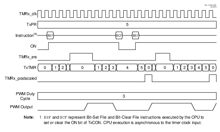
In the Level Triggered Hardware Limit Timer modes the counter is
reset by high or low levels of the external signal TMRx_ers, as shown in Figure 1. Selecting MODE = ‘b00110 will cause the timer to reset on a low-level
external signal. Selecting MODE = ‘b00111 will
cause the timer to reset on a high-level external signal. In the example, the counter is
reset while TMRx_ers = 1. ON is controlled by
BSF and BCF instructions. When ON = 0, the external signal is ignored.
When the CCP uses the timer as the PWM time base, then the PWM output will be set high when the timer starts counting and then set low only when the timer count matches the CCPRx value. The timer is reset when either the timer count matches the TxPR value or two clock periods after the external Reset signal goes true and stays true.
The timer starts counting, and the PWM output is set high, on either the clock following the TxPR match or two clocks after the external Reset signal relinquishes the Reset. The PWM output will remain high until the timer counts up to match the CCPRx pulse-width value. If the external Reset signal goes true while the PWM output is high, then the PWM output will remain high until the Reset signal is released allowing the timer to count up to match the CCPRx value.
‘b00111)