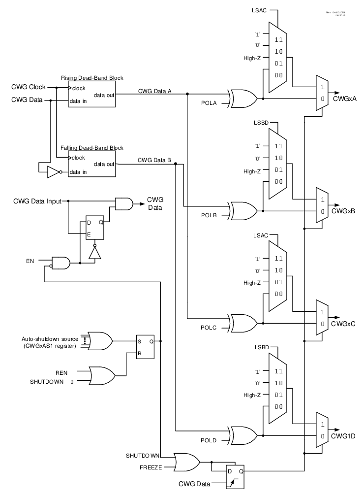
In Half Bridge mode, two output signals are generated as true and inverted versions of the input as illustrated in Figure 1. A nonoverlap (dead band) time is inserted between the two outputs to prevent shoot-through current in various power supply applications. Dead-band control is described in the Dead-Band Control section. The output steering feature cannot be used in this mode. A basic block diagram of this mode is shown in Figure 2.
The unused outputs CWGxC and CWGxD drive similar signals as CWGxA and CWGxB, with polarity independently controlled by the POLC and POLD bits, respectively.
Figure 1. CWG Half Bridge Mode
Operation
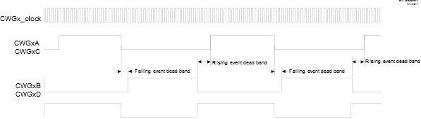
Figure 2. Simplified CWG Block Diagram
(Half Bridge Mode, MODE =
‘b100)