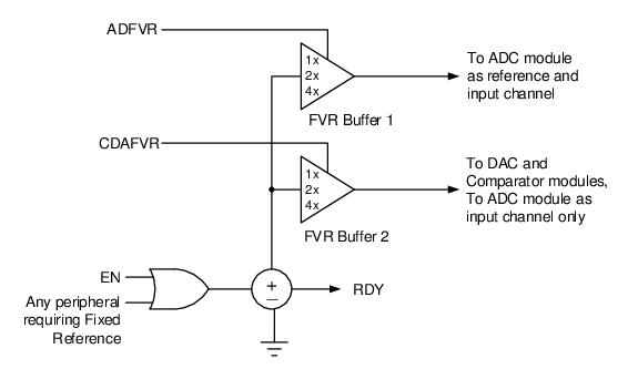
The output of the FVR is routed through two independent programmable gain amplifiers. Each amplifier can be programmed for a gain of 1x, 2x or 4x, to produce the three possible voltage levels.
The ADFVR bits are used to enable and configure the gain amplifier settings for the
reference supplied to the ADC module. Refer to the “ADCC - Analog-to-Digital Converter
with Computation Module” chapter for additional information.
The CDAFVR
bits are used to enable and configure the gain amplifier settings for the reference
supplied to the DAC and comparator modules. Refer to the “DAC - Digital-to-Analog
Converter Module” and “CMP - Comparator Module” chapters for additional
information.
Refer to the figure below for the block diagram of the FVR module.
Figure 1. Fixed Voltage Reference Block
Diagram