Figure 1. Reset, Watchdog Timer, and
Power-up Timer Timing
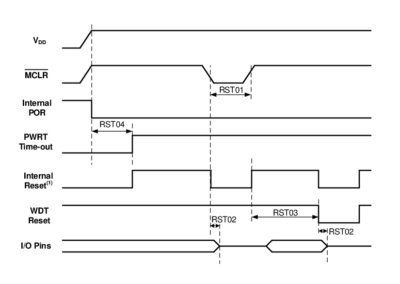
Note:
- 1.Asserted low.
Figure 2. Brown-out Reset Timing and
Characteristics
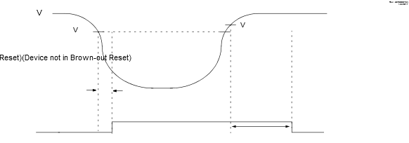
Note:
- 1.Delay period is determined by the PWRTS bits in the Configuration Word register.
| Standard Operating Conditions (unless otherwise stated) | |||||||
|---|---|---|---|---|---|---|---|
| Param. No. | Sym. | Characteristic | Min. | Typ. † | Max. | Units | Conditions |
| RST01* | TMCLR | MCLR Pulse Width Low to ensure Reset | — | — | — | μs | |
| RST02* | TIOZ | I/O high-impedance from Reset detection | — | — | — | μs | |
| RST03 | TWDT | Watchdog Timer Time-out Period | — | — | — | ms | WDTCPS = 00100 |
| RST04* | TPWRT | Power-up Timer Period | — | — | 64 | ms | |
| RST05 | TOST | Oscillator Start-up Timer Period(1,2) | — | 1024 | — | TOSC | |
| RST06 | VBOR | Brown-out Reset Voltage |
— — |
2.65 1.9 |
— — |
V V |
BORV = BORV = |
| RST07 | VBORHYS | Brown-out Reset Hysteresis | — | — | — | mV | BORV = 0 |
| RST08 | TBORDC | Brown-out Reset Response Time | — | — | — | μs | |
|
* These parameters are characterized but not tested. † Data in “Typ” column is at 3.0V, 25°C unless otherwise stated. These parameters are for design guidance only and are not tested. Notes:
|
|||||||