The Configurable Logic Cell (CLC) module provides programmable logic that operates outside the speed limitations of software execution. The logic cell takes up to 256 input signals and, through the use of configurable gates, reduces those inputs to four logic lines that drive one of eight selectable single-output logic functions.
Input sources are a combination of the following:
- I/O pins
- Internal clocks
- Peripherals
- Register bits
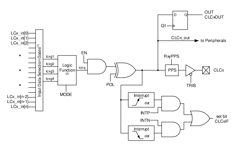
The following figure is a simplified diagram showing
signal flow through the CLC. Possible configurations include:
- Combinatorial
Logic
- AND
- NAND
- AND-OR
- AND-OR-INVERT
- OR-XOR
- OR-XNOR
- Latches
- SR
- Clocked D with Set and Reset
- Transparent D with Set and Reset