The SPI bus can sometimes be connected in a daisy-chain configuration. The first client output is connected to the second client input, the second client output is connected to the third client input, and so on. The final client output is connected to the host input. Each client sends out, during a second group of clock pulses, an exact copy of what was received during the first group of clock pulses. The whole chain acts as one large communication shift register. The daisy-chain feature only requires a single Client Select line from the host device.
In a daisy-chain configuration, only the most recent byte on the bus is required by the client. Setting the Buffer Overwrite Enable (BOEN) bit will enable writes to the SSPxBUF register, even if the previous byte has not been read. This allows the software to ignore data that may not apply to it.
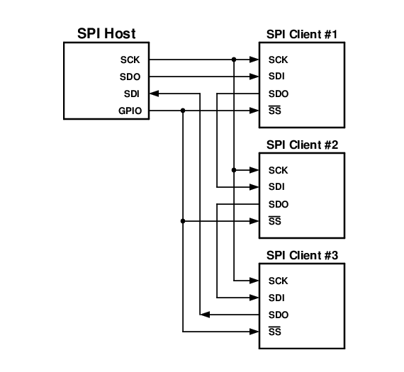
Figure 1 shows the block diagram of a typical daisy-chain connection when operating in SPI mode.