- 1.The Host generates a Start condition by setting the SEN bit.
- 2.SSPxIF is set by hardware on completion of the Start.
- 3.SSPxIF is cleared by software.
- 4.The MSSP module will wait the required start time before any other operation takes place.
- 5.Software loads the SSPxBUF with the client address and the R/W bit. In Host Transmit mode, the R/W value is zero.
- 6.Address is shifted out the SDA pin until all eight bits are transmitted. Transmission begins as soon as SSPxBUF is written to.
- 7.The MSSP module shifts in the ACK value from the client device and writes its into the ACKSTAT bit.
- 8.The MSSP module generates an interrupt at the end of the ninth clock cycle by setting the SSPxIF bit.
- 9.Software loads the SSPxBUF with eight bits of data.
- 10.Data is shifted out the SDA pin until all eight bits are transmitted.
- 11.The MSSP module shifts in the ACK bit from the client device and writes its value into the ACKSTAT bit.
- 12.Steps 8-11 are repeated for all transmitted data bytes.
- 13.The user generates a Stop or Restart condition by setting the PEN or RSEN bits, respectively. An Interrupt is generated once the Stop/Restart condition is complete.
Figure 1. I2C
Host Mode Waveform (Transmission, 7-Bit Address)
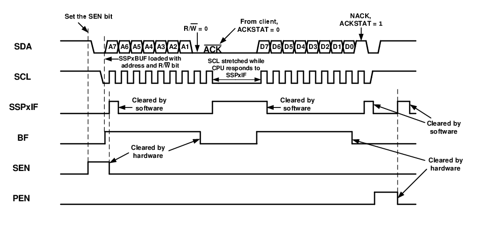
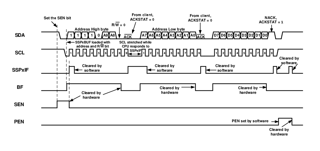
Figure 2. I2C Host Mode Waveform
(Transmission, 10-Bit Address)