Depending on the number of bits implemented in the CLCnSELy registers, there can be as many as 256 sources available as inputs to the configurable logic. Four multiplexers are used to independently select these inputs to pass on to the next stage as indicated on the left side of the following diagram.
Data inputs in the figure are identified by a generic numbered input name.
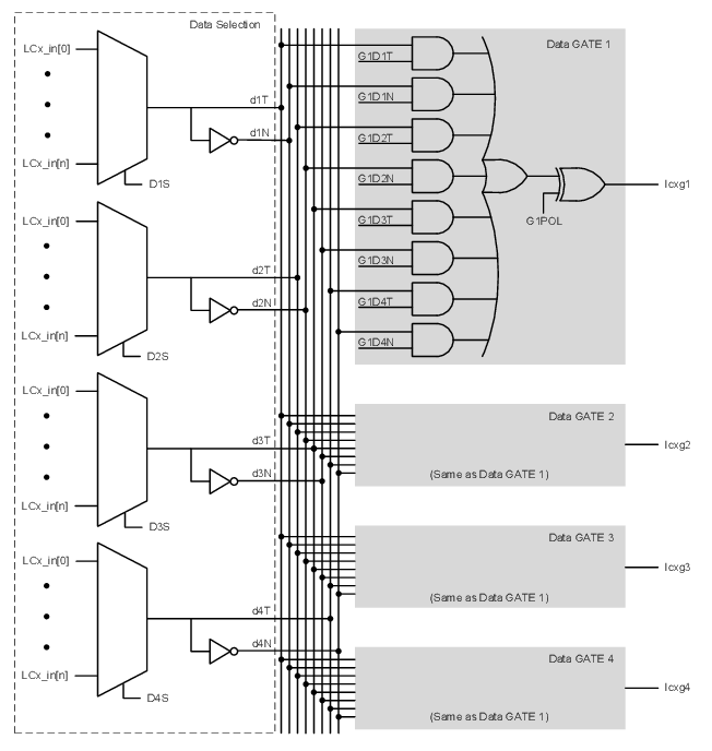
The CLC Input Selection table correlates the generic input name to the actual signal for each CLC module. The table column labeled ‘DyS Value’ indicates the MUX selection code for the selected data input. DyS is an abbreviation for the MUX select input codes, D1S through D4S, where ‘y’ is the gate number.