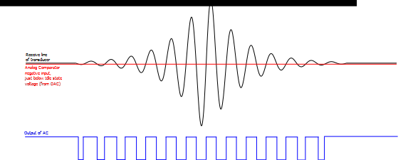
As can be seen in figure Oscilloscope Screen Capture Indicating Reflected Signal Attenuation below here, the reflected signal is significantly attenuated compared to the transmitted PWM signal. To handle this, the receive line of the transducer is fed into the analog comparator, which has a compare value set just below the Idle state voltage (half of the supply voltage to the transducer). This value is very specifically generated by the Digital-to-Analog Converter (DAC) module. The result will be as indicated in figure Functionality of the Analog Comparator in Detecting the Attenuated Reflected Signal. This procedure enables the reflected signal to be detected as soon as it arrives, despite its attenuation.

The DAC is set up to produce this value just below the idle voltage of the ultrasonic transducer. The DAC output value has to be configured to be close enough so that the reflected signal is detected as soon as it arrives despite its attenuation, but not so close that the AC picks up noise. To aid with filtering noise, the hysteresis setting of the AC can be enabled; this means the DAC value can be slightly closer to the idle voltage of the transducer, thereby increasing the accuracy of the distance measurements.