The on-board debugger and level shifters can be completely disconnected from the AVR64DD32.
The block diagram below shows all connections between the debugger and the AVR64DD32. The rounded boxes represent connections to the board edge. The signal names shown are also printed in silkscreen on the bottom side of the board.
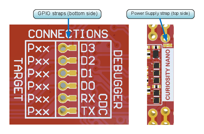
To disconnect the debugger, cut the straps shown in Figure 2.
Attention: Cutting the GPIO straps to the on-board debugger will disable the
virtual serial port, programming, debugging, and data streaming. Cutting the power
supply strap will disconnect the on-board power supply.
Tip: Reconnect any cut connection
by using solder. Alternatively, mount a 0Ω 0402 resistor.
Tip: When the debugger is
disconnected, an external debugger can be connected to holes, as shown in Figure 2. Details about
connecting an external debugger are described in Connecting External Debuggers.
Figure 1. On-Board Debugger Connections
Block Diagram
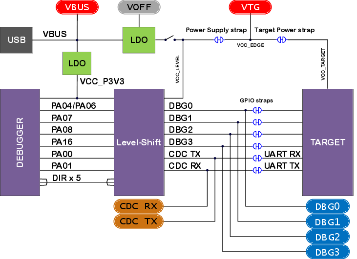
Figure 2. On-Board Debugger Connection Cut Straps