Debug GPIO channels are timestamped digital signal lines connecting the target application to a host computer visualization application. They are typically used to plot low-frequency events on a time axis – for example, when given Application state transitions occur.
The figure below shows the monitoring of the Digital state of a mechanical switch
connected to a debug GPIO in MPLAB Data Visualizer.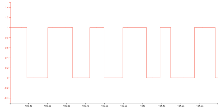
Figure 1. Monitoring Debug GPIO with MPLAB® Data Visualizer
Debug GPIO channels are timestamped, so the resolution of DGI GPIO events is determined by the resolution of the DGI Timestamp module.
Important: Although signal
bursts of higher frequency can be captured, the frequency range of signals for which
debug GPIO can be used is up to about 2 kHz. Attempting to capture signals above
this frequency will result in data saturation and overflow, which may cause the DGI
session to be aborted.