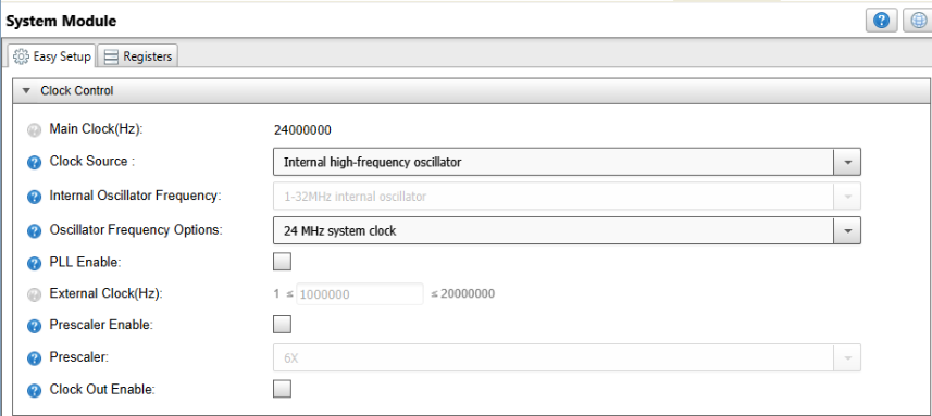
System Module
- Clock source: Internal high-frequency oscillator
- Oscillator frequency: 24 MHz
- Prescaler: Disabled
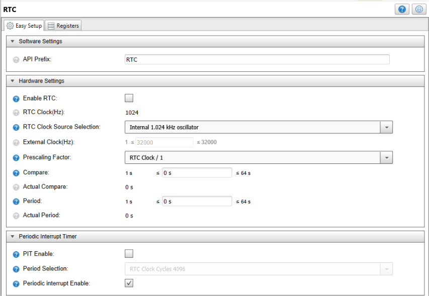
RTC
- RTC Clock Source Selection: Internal 1.024 kHz oscillator
- PIT: Periodic Interrupt Enable: Checked
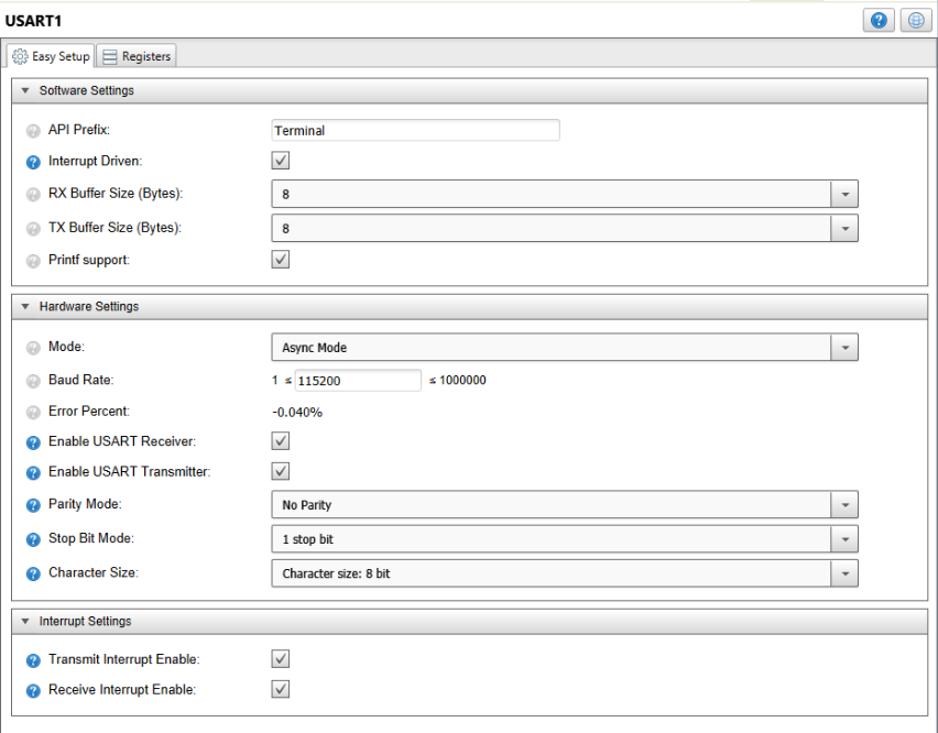
USART
- API Prefix: Terminal
- Interrupt Driven: Checked
- Printf Support: Checked
- Baud Rate: 115200
- Transmit Interrupt Enable: Checked
- Receive Interrupt Enable: Checked
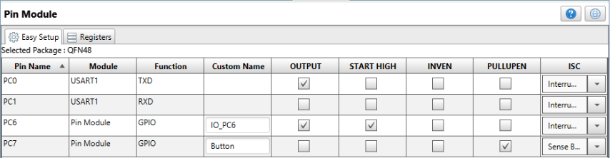
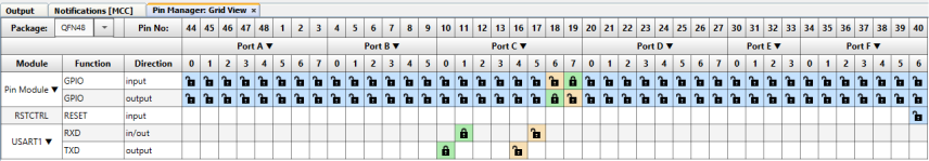
Pin Module and Manager
- PC0 as output TXD
- PC1 as input RXD
- PC6 set as output and Start High
- PC7 named ‘Button’, Pull-up enabled and Interrupt-on-Sense both edges
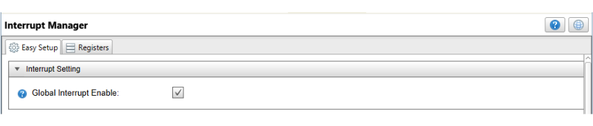
Interrupt Manager
- Global Interrupt Enable: Checked
In the generated pin_manager.c file, the following rows are modified
to set all the unused pins to output so that the power readings are not
perturbed.
    /* DIR Registers Initialization */
    PORTA.DIR = 0xFF;
    PORTB.DIR = 0xFF;
    PORTC.DIR = 0x7D;
    PORTD.DIR = 0xFF;
    PORTE.DIR = 0xFF;
    PORTF.DIR = 0xFF;
The main.c file contains the code for the various instructions that
can be called from USART.
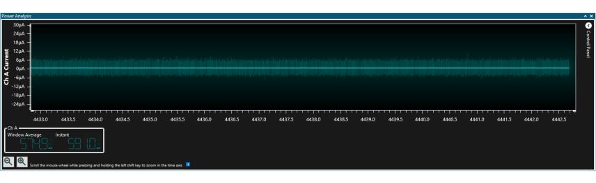
Active Mode
This mode is accessed by sending an ‘a’ or an ‘A’ character through USART. It keeps the microcontroller active and can be left by sending a new character.
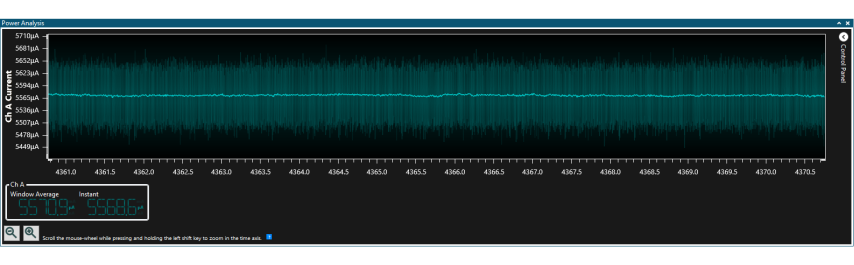
This is the average power consumed when the high-frequency oscillator is running at full power.
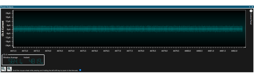
Idle Sleep Mode
This mode is accessed by sending an ‘i’ or ‘I’ character through USART. It puts the microcontroller into Idle sleep mode where the high-frequency oscillator is set to a lower consumption mode, but it is still operational and ready to act when the microcontroller exits a sleep mode. This mode can be left by sending a new character through USART.
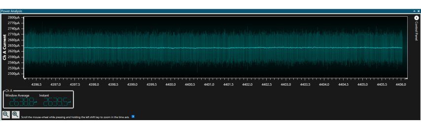
The power consumed by the high-frequency oscillator in Idle sleep mode is approximately half the power consumed in Active mode. If more peripherals are running in this mode, then the power consumption will be higher.
Standby Sleep Mode
This mode is accessed by sending an ‘s’ or ‘S’ character through USART. It puts the microcontroller into Standby sleep mode. No peripherals are running in Standby sleep mode in this program, so the consumed power is just due to the oscillators. To exit this mode, the on-board button must be pressed, and then, a new character must be sent.
The power consumed in this mode is highly dependent on the number of peripherals that are running. In this example, no peripherals are running, so the consumed power is similar to the Power-Down sleep mode.
Power-Down Sleep Mode
This mode is accessed by sending a ‘p’ or ‘P’ character through USART. It puts the microcontroller into Power-Down sleep mode. The high-frequency oscillator is turned off, and only the 32.768 kHz internal oscillator is running. To exit this mode, the on-board button must be pressed, and then, a new character must be sent.
The power consumed in this mode is approximately the same as the power consumed in Standby sleep mode without active peripherals.
Cycle Instruction
This instruction is started by sending a ‘c’ or ‘C’ character through USART. It will cycle through all the previous modes with a four-second interval between them timed by the PIT. This instruction runs to completion and cannot be stopped until then. After it ends, a new character can be sent.
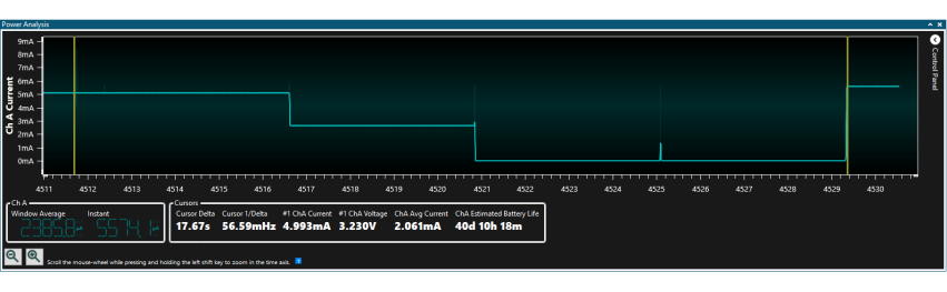
Figure 11 shows the differences between the power consumption of various modes. Idle sleep mode consumes about half the power the Active mode does, while Standby and Power-Down sleep modes are almost nothing compared to the other ones.
Deep Sleep and Short Wake-up Instruction
This instruction starts by sending a ‘w’ or ‘W’ character through USART. It will simulate a typical sensor application powered by a battery. It spends four seconds in Power-Down sleep mode and then sends a message that simulates reading sensors for a short time. This cycle repeats four times and is timed by the PIT. This instruction runs to completion and cannot be stopped until then. After it ends, a new character can be sent.
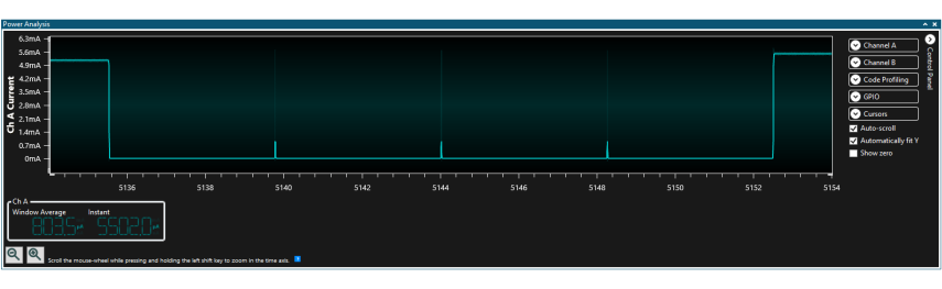
The short current spikes represent the times the microcontroller wakes up to read the sensors.
Default Command
Any other character except the ones presented before will make the microcontroller print the menu with the available commands again.