A mutual capacitance touch surface consists of ‘row’ and ‘column’ electrodes, which are implemented as X and Y, respectively. Each row or column is measured, and the data are combined to implement slider functionality in both the horizontal and vertical directions.
Interleaved Surface
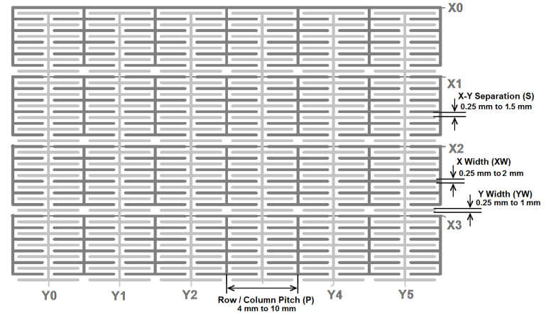
The interleaved slider pattern may be extended to two dimensions to form an interleaved surface sensor. The surface pattern requires two routing layers to allow crossovers as each row must be joined from left to right and each column from top to bottom.
The sensor may be implemented on a single layer with connections only on the second layer, or as a split-level design with X electrodes on the layer further from the touch cover and Y electrodes on the closer layer.
| Min. | Typical | Max. | |
|---|---|---|---|
| Row/Column Pitch (P) | 4 mm | 6 mm | 10 mm |
| X Electrode Width (XW) | 0.25 mm | 0.5 mm | 2 mm |
| Y Electrode Width (YW) | 0.25 mm | 0.5 mm | 1 mm |
| XY Separation (S) | 0.25 mm | 0.5 mm | 1.5 mm |
Diamond Pattern
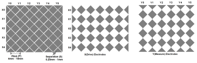
The diamond pattern presented in Surface Sensor Design for the self-capacitance surface may also be implemented as a mutual capacitance sensor.
Horizontal sensor nodes may be driven as X lines, while vertical nodes are measured as Y or vice versa. The X- and Y- electrodes may be arranged as a coplanar design or as a split-level configuration with X-electrodes at the rear, as described above for buttons, sliders, and wheels.
| Min. | Typical | Max. | |
|---|---|---|---|
| Row/Column Pitch (P) | 4 mm | 6 mm | 10 mm |
| XY Separation (S) | 0.25 mm | 0.5 mm | 1 mm |
Similarly, the flower pattern surface described in Surface Sensor Design may be used for the mutual capacitance surface.
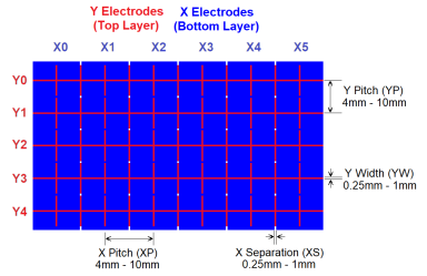
Flooded X Surface
The sensor is formed with X electrodes as vertical bars to the rear, and Y electrodes as narrow traces horizontally spaced on the top layer. Interpolation along Y nodes provides the vertical position, interpolation along X nodes the horizontal.
| Min. | Typical | Max. | |
|---|---|---|---|
| Y Pitch (YP) | 4 mm | 6 mm | 10 mm |
| Y Width (YW) | 0.25 mm | 0.5 mm | 1 mm |
| X Pitch (XP) | 4 mm | 6 mm | 10 mm |
| X Separation | 0.25 mm | 0.5 mm | 1 mm |