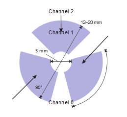
A wheel sensor consists of a row of three or more sensor electrodes, which are arranged in a circle.
A wheel sensor operates in the same way as a slider sensor, with the single exception being that it is wrapped around from Channel n to Channel 0, so there are no end electrodes in the design.
As with a slider, a wheel can be made with discrete non-overlapping sensors.
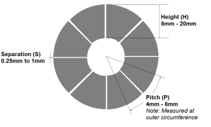
A larger wheel may be implemented by increasing the number of sensor keys used or by increasing the segment interpolation, as in the case of the slider.
| Min. | Typical | Max. | |
|---|---|---|---|
| Wheel Height (H) | 8 mm | 12 mm | 20 mm |
| Electrode pitch (P) | 4 mm | 6 mm | 8 mm |
| Electrode Separation (S) | 0.25 mm | 0.5 mm | 1 mm |
As with other sensors, sharp corners in the electrodes need to be rounded to minimize susceptibility to ESD. The points of the triangles forming the interpolation must be truncated to a rounded end of ~2 mm diameter.
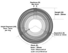
Wheel electrodes must be close together for continuous sensitivity, but too little separation can cause increased loading capacitance, as each sensor electrode has a parasitic load against its neighboring electrodes. The spacing should be increased up to a maximum of 1.5 mm in the cases when there are long parallel edges between electrodes due to extensive interpolation.
| Min. | Typical | Max. | |
|---|---|---|---|
| Slider Height (H) | 8 mm | 12 mm | 20 mm |
| Height Segment (HS) | 4 mm | 6 mm | 8 mm |
| Electrode Pitch (P) | 8 mm | 16 mm | 30 mm |
| Electrode Separation (S) | 0.5 mm | 1 mm | 1.5 mm |
| Deadzone (D) | — | — | 4 mm |