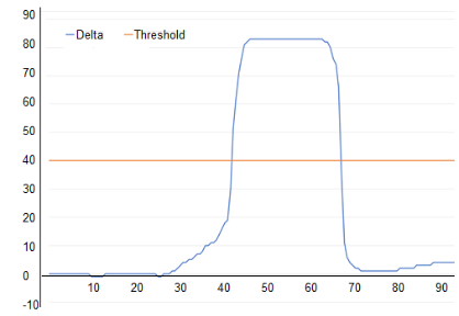
The simplest implementation of a capacitive sensor is a button. A button is a single sensor and is interpreted as a binary state: In Detect or Out of Detect. When the touch delta – the digitized measurement of touch capacitance Ct – exceeds the Touch Threshold, the sensor is In Detect.
The sensor is touched by a user touch, or a touch emulator such as a conductive bar, which is connected to earth via a human body model circuit. The threshold is set to a proportion – often 50% – of the maximum touch delta.
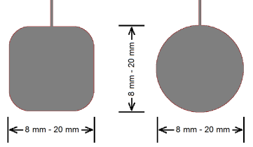
Electrode Shapes
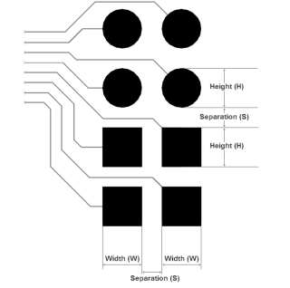
A touch electrode is a patch of conductive material, such as copper on a non-conductive substrate. Common shapes are round or rectangular solid areas, however, any shape with sufficient touch contact area may be used. Corners must be rounded to reduce the concentration of electric fields, which may increase the occurrence of Electrostatic Discharge (ESD) to the sensor pad.
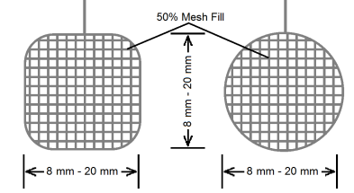
It is also possible to use a hatched pattern (such as a 50% mesh fill) for the electrode if desired. This will not only reduce the load capacitance of the sensor electrode but also reduce the area of one capacitor plate with the touch resulting in a proportional drop in sensitivity.
Touch Target Size
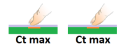
The touch sensor electrode must be large enough that a touch contact does not need to be precisely placed to activate the sensor. If the sensor electrode is smaller than the user’s fingertip, then sensitivity is reduced by the smaller effective area. For example, an 8 mm diameter touch sensor with an 8 mm diameter touch contact will only show maximum delta when the contact is placed directly at the center of the electrode.
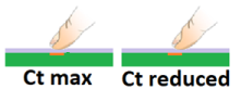
By increasing the size of the sensor, the user may place a contact anywhere over the sensor area with no loss in sensitivity, as long as the entire touch area is kept within the perimeter of the touch sensor. The effective parallel area of the touch contact is limited by the size of the user’s fingertip, not the sensor area.
Hand Shadow
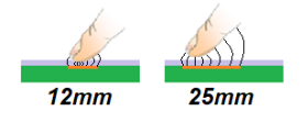
An unnecessarily large sensor electrode will show an unintended proximity effect due to coupling to an approaching hand before the fingertip makes contact. The contact capacitance of the fingertip is not easily distinguished from the approach capacitance.
Pin Loading
Large sensors have higher default capacitance, and the effect is increased if the sensor is located close to other circuitry including other sensors.
Larger load capacitance causes increased time constant, and the sensor takes longer to charge, discharge, and measure. This can lead to deterioration in touch detect latency and power consumption.
Depending on the measurement technology, high-capacitance sensors may have reduced sensitivity or may exceed the range of the analog front-end compensation circuitry.
Electrode Separation
Individual sensor electrodes must be sufficiently separated so that touching one key does not cause an unintentional capacitance change on the neighboring keys, which could be misidentified as another touch contact. The recommended spacing between sensor electrodes is 4 mm + touch cover thickness. In many cases, it is necessary to trade off sensor size and sensor separation to accommodate a dense user interface layout.
| Min. | Typical | Max. | |
|---|---|---|---|
| Height (H) | 8 mm | 12 mm | 20 mm |
| Width (W) | 3 mm | 6 mm | 20 mm |
| Separation (S) | 3 mm | 6 mm | - |