- Usually connected to DC ground
- May also use VDD or any ground-referenced DC level
- Rear copper flood (on a layer behind the electrodes) prevents touch or EMI from behind
- Coplanar flood (around the electrodes on the same layer) provides better isolation of touch sensors
- May be hatched to reduce the capacitive load
- Detrimental to moisture tolerance
Effect of Ground Loading
DC or ground loading adds directly to the sensor base capacitance, which increases the RC time constant and thus the acquisition time.
Passive sensors are usually driven to a DC level, and the traces to these idle channels behave as though connected to the ground. If a trace leading to Key 1 is routed close to Key 2, then Key 2 is loaded as though to a ground trace.
Ground referenced electrodes or traces close to the touch sensor will cause a reduction in touch sensitivity as the electric field emitted by the sensor electrode is attracted to the ground plane. This reduces the strength of the electric field available to interact with the user’s touch contact.
Rear Ground Shield
Sometimes it is desirable to shield an electrode on its rear side to prevent false detection from moving parts behind, or to prevent interference from switching signals, for example, from backlighting or driver circuitry.
If a driven shield cannot be implemented, then a ground plane may be used. This must be connected directly to the circuit ground at a single point.
A rear ground plane will most likely significantly reduce the sensitivity of the touch sensors, as the DC ground attracts the electric field emitted by the touch sensor electrode. This must be taken into consideration, particularly where the touch cover may be thicker than the separation between electrode and ground layers.
To alleviate this problem, the electrode and ground plane must be separated by the maximum distance possible. For example, on a multilayer printed circuit board PCB, the touch sensors must be on the top layer and the ground on the bottom.
Additionally, the ground shield may be reduced to 50% or 25% hatched fill, which reduces the sensor loading while still providing some shielding effect.
If the application does not risk accidental touch contact from the rear of the sensor board, the rear ground plane may be cut out behind the sensor keys. This reduces the capacitive loading of the sensors while providing sensor isolation from other circuit components or EMI.
Coplanar Ground Shield
A coplanar ground shield may be implemented to improve the isolation between the touch sensors, to reduce EMI to the touch sensors, and to reduce the interference caused by common-mode noise when a touch contact is present.
Use a solid fill as a coplanar shield since the shield does not overlap the touch area.
To minimize the loss in sensitivity, the ground shield must be kept at a distance from any touch sensor of approximately 2 mm.
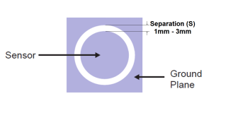
| Type | Min. | Typical | Max. |
|---|---|---|---|
| Sensor – Gnd Separation (S) | 1 mm | 2 mm | 3 mm |
Example Layout
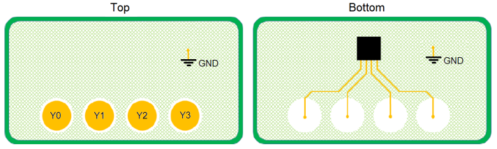
Increasing or decreasing the gap between the sensor and the ground affects the sensor operation in several ways.
Sensor capacitance is increased when the gap is reduced. This proportionally increases the sensor time constant and thus the total measurement time. Large sensor electrodes or electrodes with complex perimeter shapes must have an increased gap to avoid excessive sensor capacitance.
Noise tolerance is reduced by increasing the gap. The ground shield improves noise tolerance by providing a lower impedance path to ground for noise injected via the touch cover.
Moisture tolerance is improved by increasing the gap. To trigger due to water on the touch cover, the water must bridge between the sensor electrode and another path to the ground. Placing a ground shield very close to the sensor electrode makes it possible for a very small amount of water to bridge the gap.