- Usually connected to DC ground
- May also use VDD or any ground-referenced DC level
- Rear flood prevents touch or EMI from behind
- Coplanar flood provides better isolation of touch sensors
- May be hatched to reduce the capacitive load
- Detrimental to moisture tolerance
Rear Ground Shield
Sometimes it is desirable to shield an electrode on its rear side to prevent false detection from the rear, or to prevent interference from switching signals from, e.g., backlighting or other power driver circuitry.
A ground plane may be used. This must be connected directly to the circuit ground at a single point.
For mutual capacitance sensors, the effect of a ground area behind the sensor node reduces the overall capacitance of the sensor node. This can be beneficial in some applications as it allows more keys to be lumped together. However, the sensor’s time constant may be increased by loading the Y-line electrode.
A rear ground plane may significantly reduce the sensitivity of the touch sensors, as the DC ground attracts the electric field emitted by the X electrode. This must be taken into consideration, particularly where the touch cover may be thicker than the separation between sensor and ground layers.
The electrode and ground plane must be separated by the maximum distance possible. For example, on a multi-layer PCB, the touch sensors must be on the top layer and the ground on the bottom.
The ground shield may be reduced to 50% or 25% hatched fill, which alleviates the reduction in sensitivity while still providing the shielding effect.
If the application does not risk accidental touch contact from the rear of the sensor board, the rear ground plane may be cut out behind the sensors. This eliminates the desensitization of the sensors while providing isolation from other circuit components or EMI.
Coplanar Ground Shield
A coplanar ground shield may be implemented to improve isolation between touch sensors and reduce EMI and common mode noise effects.
As a coplanar shield does not overlap the area of the touch sensors, a solid fill may be used.
To minimize the loss in sensitivity, the ground shield must be kept at a distance from any touch sensor of approximately 2 mm, which may be increased for better moisture tolerance. However, if it is increased beyond 5 mm, the effectiveness of the shielding is reduced.
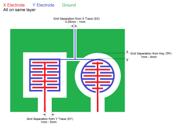
| Min. | Typical | Max. | |
|---|---|---|---|
| Ground Separation from Key (SK) | 1 mm | 2 mm | 5 mm |
| Ground Separation from Y Trace (SY) | 1 mm | 2 mm | 5 mm |
| Ground Separation from X Trace (SX) | 0.25 mm | 0.25 mm | 1 mm |