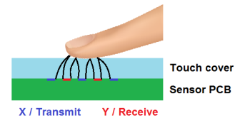
Unlike for self-capacitance measurements, there is no simple way to approximate the expected touch capacitance for a given mutual sensor layout. The parallel plate approximation is not applicable as the ‘plates’ in this case are segments of the X and Y electrodes, which are much smaller than the touch cover. The user’s touch contact is dominated by edge and point fields between the electrode pair and the fingertip.
When designing mutual capacitance sensors, the node layout may be optimized to suit application requirements such as:
- Maximum sensitivity
- Best noise tolerance
- Best water rejection
- Minimum default sensor capacitance (some acquisition technologies have a limit on the sensor capacitance)
- Minimum power consumption
- Minimum touch latency
All applications will require a trade-off between these properties, as achieving one will mean compromising others.
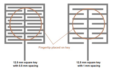
As an example, the strongest sensitivity is achieved using high interleaving of electrodes. However, achieving minimum sensor capacitance requires a larger spacing between X and Y.
Excess sensor capacitance increases acquisition time and power consumption.
Increasing X-Y separation reduces default X-Y capacitance, but it also reduces the lengths of parallel segments between the electrodes.
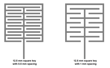
When a user touches the sensor with larger spacing, a smaller total length of parallel segments is covered by the touch. This translates to a reduced X-Y field interaction and hence a proportional reduction in sensor sensitivity.