A wheel sensor operates in the same way as a slider sensor, with the single exception that it is wrapped around from Channel n to Channel 0 so there are no end electrodes in the design.
The sensor width must be between 8-20 mm wide. To avoid excess XY capacitance – and an associated increase in acquisition time – the electrode spacing must be increased for larger sensors.
The electrode segment width must usually be the minimum track width available but may be increased up to 1 mm where the sensors are formed on a high sheet resistance material such as ITO.
Interleaved Wheel
Like the interleaved slider, the simplest implementation is a coplanar interleaved wheel. X and Y electrodes are formed on the same PCB layer. The design may also be split across two PCB layers to reduce default capacitance, with the X electrodes on the layer further from the touch cover.
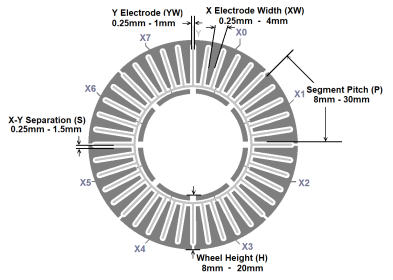
| Min. | Typical | Max. | |
|---|---|---|---|
| Wheel Height (H) | 8 mm | 12 mm | 20 mm |
| Segment width | 8 mm | 12 mm | 30 mm |
| X electrode width | 0.25 mm | 0.5 mm | 4 mm* |
| Y electrode width | 0.25 mm | 0.5 mm | 1 mm |
| XY spacing | 0.25 mm | 0.5 mm | 1.5 mm |
Flooded X Wheel
As the X electrodes in a flooded X design sit on a separate PCB layer, spatial interpolation may be extended without complex routing around the Y electrodes. This allows the flooded X design to provide improved linearity over the interleaved layout. The X layer pattern for a flooded X slider is identical to the interpolated self-capacitance wheel presented in the previous section.
The wheel is made up of concentric segments of 4-6 mm, each containing the interleaved electrode pattern. The sensor must include enough segments to make up the desired width.
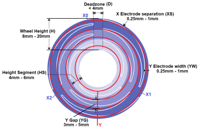
| Min. | Typical | Max. | |
|---|---|---|---|
| Wheel Height (H) | 8 mm | 12 mm | 20 mm |
| Height Segment (HS) | 4 mm | 5 mm | 6 mm |
| X Electrode Pitch (P) | 8 mm | 16mm | 30 mm |
| X Electrode Separation (XS) | 0.25 mm | 0.5mm | 1 mm |
| X Electrode Overlap (XO) | 1 mm | 2 mm | 3 mm |
| Deadzone (D) | - | 2 mm | 4mm |
| Y Electrode Width (YW) | 0.25 mm | 0.5 mm | 1 mm |
| Y Gaps (YG) | 3 mm | 4 mm | 5 mm |
Resistive Interpolation
In both coplanar and flooded X designs, it is possible to reduce the number of sensor node measurements while maintaining linearity by resistive interpolation of some sensor nodes.
A minimum of three directly routed X-electrodes is required, placed symmetrically around the wheel. Intermediate nodes are joined with a series of resistors that form a resistive divider driving each intermediate node at a fraction of the X-drive voltage.
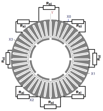
A touch contact on an intermediate node causes a proportional touch delta on each of the neighboring direct nodes. Reduced pulse amplitude causes proportionally less touch delta at these locations, allowing interpolation between measured nodes.
Segment interpolation resistors Rxi must be selected so that the total series combination between each pair of directly connected X lines is in the range of 10-20 Ohm.