The last step of this project is to implement the start position of the shaft. The metronome can be powered off while running. Every time the metronome is powered on, it is found in the position where it last stopped, a position unknown to the user. Thus, the shaft needs to be set in a known position.
Setting the shaft in a known position is possible because the Switec stepper motor has an internal stop mechanism. This allows rotation within a known number of steps (315, for the motor used in this application) between two positions (zero and the maximum value).
The positioning algorithm uses these details and starts with setting the shaft to position zero, by running the 320 steps in counterclockwise direction, followed by a known number of steps in clockwise direction. At that moment, the position of the shaft is known.
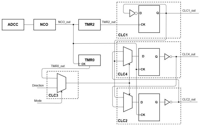
The solution must allow control of direction of rotation and the number of steps to be run, but the motor also needs to be able to run as a metronome. This is done using the CLC3 in 2:1 multiplexer configuration.
As data inputs, the CLC3 has TMR0_out and a signal called ‘Direction’, whose value indicates the direction of rotation, clockwise or counterclockwise.
As selection input, the CLC3 has another signal, called ‘Mode’, whose value indicates the manner of running, free run or metronome.
Both the ‘Direction’ and ‘Mode’ are non-periodical square wave signals. They can be configured by the user either in software, or in hardware, by routing them to input pins.
In order to control the number of steps to be run in each direction, the desired value must be written to the Timer0 period register. If this value exceeds the maximum value of period register, a prescaler for the Timer0 clock signal can be used.
The output from CLC3 (CLC3_out) now represents the selection input of the multiplexers from the CLC2 and CLC4.
| Mode | TMR0_out | Direction | Behavior |
|---|---|---|---|
| 0 | 0 | 0 | Metronome |
| 0 | 0 | 1 | Metronome |
| 0 | 1 | 0 | Metronome |
| 0 | 1 | 1 | Metronome |
| 1 | 0 | 0 | Run clockwise |
| 1 | 0 | 1 | Run counterclockwise |
| 1 | 1 | 0 | Run clockwise |
| 1 | 1 | 1 | Run counterclockwise |
The following figure offers a better visualization and understanding of the peripherals connections and how the signals are obtained.