Using the previously described circuit, the motor can be driven in only one direction (clockwise) and with a specific speed. But a metronome requires alternating movements in both clockwise and counterclockwise directions.
In order to indicate the direction of movement, a periodical signal was generated. The signal has a 50% duty cycle. For half of its period, the metronome will run clockwise, and for the other half, it will run counterclockwise.
Timer0 was configured to generate this signal and it has NCO_out as clock input. Every time its count register reaches the period register, the Timer0 output (TMR0_out) signal toggles.
Depending on the direction of rotation, the signals that drive the motor exhibit different waveforms.
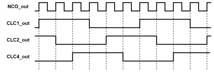
As shown in Figure 1, for counterclockwise movement, NCO_out remains the starting point for generating the waveforms and the CLC1_out is still obtained similarly to how it was described in the section above.
- CLC4_out is represented by CLC1_out delayed by one NCO_out period and then inverted.
- CLC2_out is represented by CLC4_out delayed by one NCO_out period and inverted, which is equivalent with CLC1_out delayed by two NCO_out periods.
- CLC2_out is represented by CLC1_out delayed by one NCO_out period and then inverted.
- CLC4_out is represented by CLC2_out delayed by one NCO_out period and inverted, which is equivalent with CLC1_out delayed by two NCO_out periods.
The only difference between the waveforms of the two directions of movement is the number of delays applied to CLC1_out. This is reflected in the order of the CLCs. For clockwise movement, the order of CLCs is CLC1-CLC4-CLC2, while, for counterclockwise movement, the order of CLCs is CLC1-CLC2-CLC4.
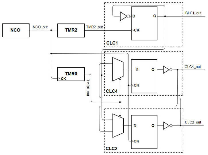
For selecting between these two directions of rotation, the CLC2 and CLC4 must be interchanged periodically. They are configured as described in Driving a Stepper Motor in a Single Direction, but a 2:1 Multiplexer (MUX) was added for each of them. The MUX will select the input signal used for the Data (D) port.
The MUX from the CLC4 has CLC2_out and CLC1_out as inputs, while the MUX from CLC2 has CLC1_out and CLC4_out as inputs. Both multiplexers have TMR0_out as selection input.
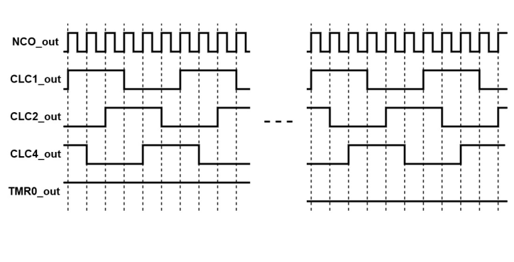
The figure below shows the NCO_out, CLC1_out, CLC2_out, CLC4_out, and
TMR0_out signals. When TMR0_out = ‘1’, the motor will run clockwise and
when TMR0_out = ‘0’, the motor will run counterclockwise.
| TMR0_out | D-FF(CLC2) input | D-FF(CLC4) input |
|---|---|---|
0
|
CLC1_out | CLC2_out |
1
|
CLC4_out | CLC1_out |
At this point, the motor works as a metronome, which only oscillates with a fixed number of beats per minute.
The following figure offers a better visualization and understanding of the peripherals connections and how the signals are obtained.