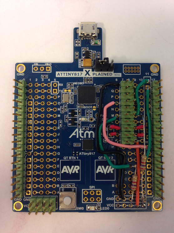
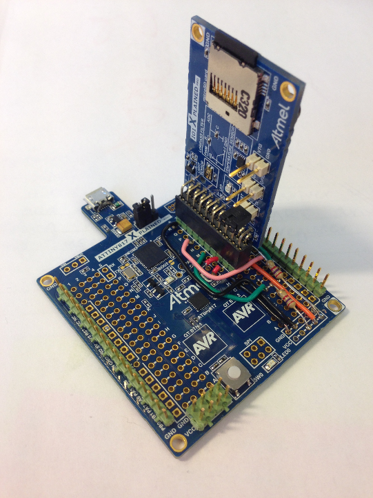
The figure below shows the finished hardware modifications with the I/O1 Xplained Pro Extension Kit mounted. In order to mount it like this, it is necessary to solder a 2x10 100 mil pin header, pull up resistors on the I2C lines, and strap wires to connect the relevant pins to the pin header.
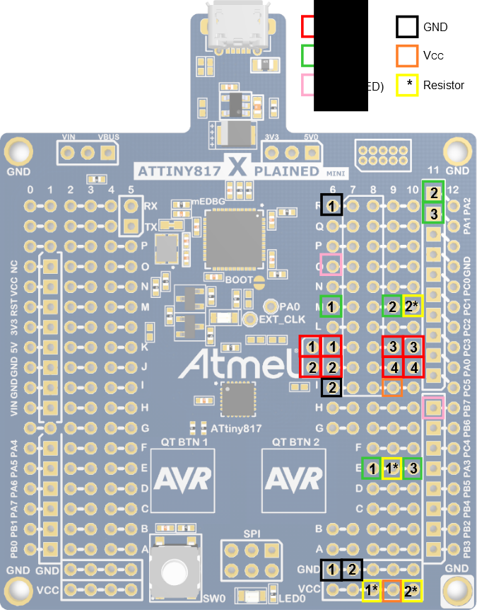
The required connections for this project include SPI (for interfacing with the SD card), I2C (for TWI communication with the temperature sensor), LED (because the one on the Xplained Mini uses the same pin as SPI_SCK), power, and ground. These connections can be seen in Figure 2, and are indicated more clearly in Figure 3. The boxes indicate the color of the wire in the photo, and where there are multiple wires of the same color, a number indicates which two boxes match. The yellow boxes with an asterisk (e.g. 1*) indicate the connection may be made with a resistor (the ones used in the photo are 2.7 kΩ).