The angular position of the rotor is vital to produce waveforms that are synchronized to the motor during the application of sinusoidal current drive. Hall effect sensors provide limited information since it can only detect the approximate position in an electrical cycle. To apply the sinusoidal current drive to the BLDC motor, a constant change in applied voltage to the MOSFET driver is required, based on the exact rotor position. In this application, a motor angular position function is designed to convert the Hall signal into equally smaller signals that represent a unit angle of rotation. It subdivides the Hall signal into smaller intervals where it acts as a trigger to change the applied voltage at a certain time and position. Several peripherals, such as timers and CCP, are used to create this function. The basic idea of this method is to count the number of system clock ticks it takes to complete a Hall period and divide it to the number of units desired for the next period, assuming that it has the same clock tick count. Since it is basically a hardware division, there will possibly be remainder clocks in the calculations. These remainder clocks will be added to the last degree/phase of the period, especially when using a slower clock source. To reduce such errors, a faster clock source is used. In this design, a 16 MHz clock is used. Figure 3-1 shows the block diagram of the implemented motor angular position scheme.
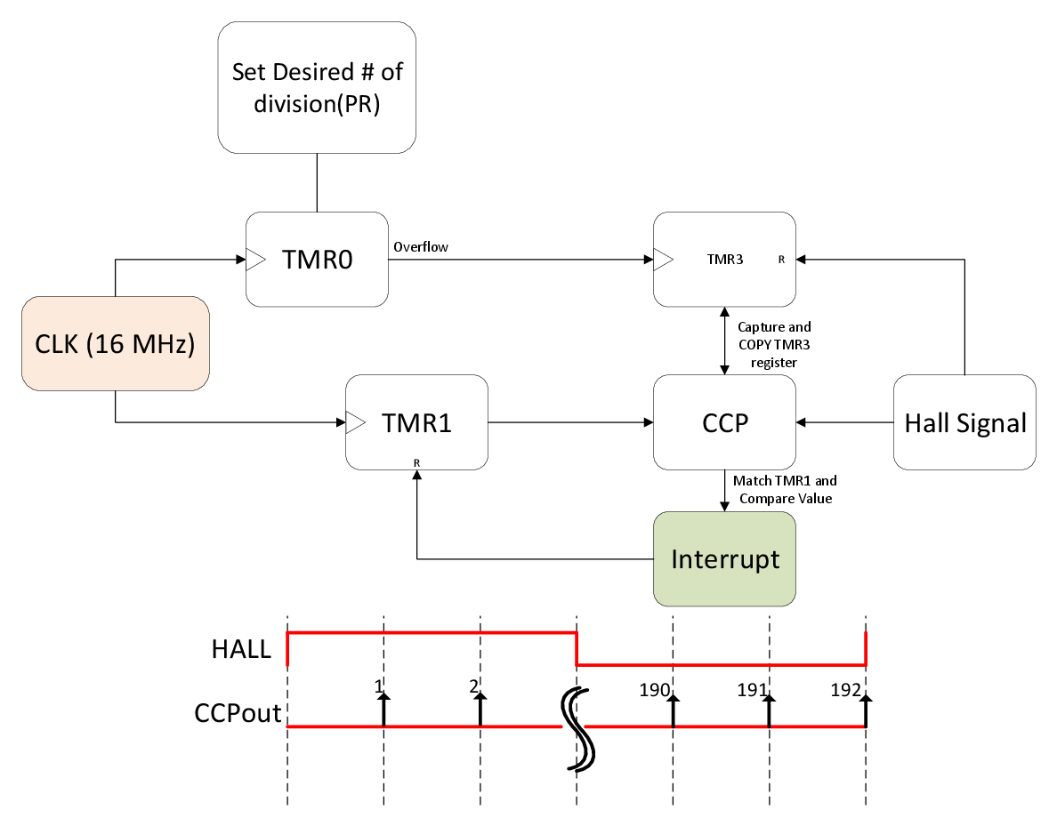
The period register of the TMR4 is used to set the desired number of divisions per Hall signal period. Since the number of arrays declared is six with 32 elements each, the number of divisions set in T4PR is 192.
TMR3 does not have a direct input connection from the TMR4 Overflow bit. By using CLC as a buffer, the TMR4 output is rerouted to the TMR3 input. It will continuously increment until the reference edge of the Hall signal is detected. Once the reference edge is detected, the value in the TMR3 register is copied to the CCP compare value, which can also be calculated using Equation 3-1. For example, a 200 Hz Hall signal takes 80,000 clock ticks. Since each TMR3 increment takes 192 clock ticks, the TMR3 counter would have registered a value of 416, when the Hall sensor edge is detected. The value is copied to the CCP Compare register, which is continuously compared to the TMR1 register. TMR1 shares the same clock source as TMR4, which is a 16 MHz clock. If matched, a CCP interrupt will occur to reload the TMR1 register and signals the DMA to increment the source address for the next PWM value. For the MCC configuration, the TMR4 register requires a time-based period and not a register value. It can be calculated using Equation 3-2. T4TMR is an 8-bit register that can store 255 values. Each clock cycle increments the T4TMR until it matches the T4PR. The clock source used is FOSC/4 of 64 MHz clock.