So far in this document, the PIC18-Q41 Mindi model has been used to simulate a non-inverting amplifier and a unity gain buffer when using the operational amplifier peripheral found on this device family.
This last example will demonstrate how Mindi can be used to simulate an inverting amplifier using the same model. An operational amplifier used in this configuration not only inverts the input signal, but also amplifies it depending on the feedback network of the circuit. Figure 1 shows the complete schematic used to simulate this design in Mindi.
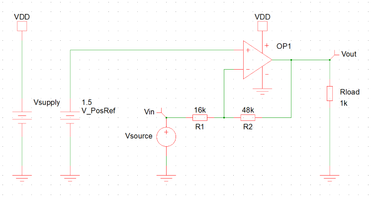
In this example, Mindi was used to simulate the sinusoidal input signal and the resulting transient response of the operational amplifier over a time of 40 ms. A bias voltage of 1.5V was connected to the non-inverting input of the operational amplifier, and a sinusoidal input with an amplitude of 400 mV and an offset of 1.5V was connected to the inverting input, along with the feedback network illustrated in the circuit shown above.
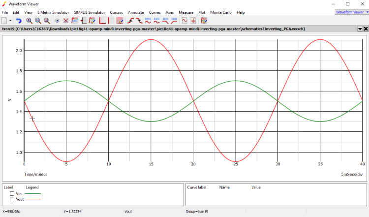
Figure 2 shows the simulation results of this circuit using the PIC18-Q41 Mindi model. The green waveform represents the input voltage source connected to the operational amplifier, and the red waveform shows the resulting signal from the operational amplifier output.