When simulating a circuit in Mindi, start by focusing on the analog device whose behavior is the primary interest of the simulation. This can be done either by finding the correct device in the model library browser and inserting it into the schematic from there, or by placing a generic version of that component into the schematic and manually filling in the parameters that determine the device behavior during simulation.
The main advantage of using devices that have model libraries instead of generic components in Mindi is that the model libraries contain the actual parametric data and electrical characteristics of that component. This allows for the simulation to be as accurate as possible. The examples discussed in this technical brief all use the PIC18-Q41 model library to simulate the circuit response of the operational amplifier peripheral found in this device family.
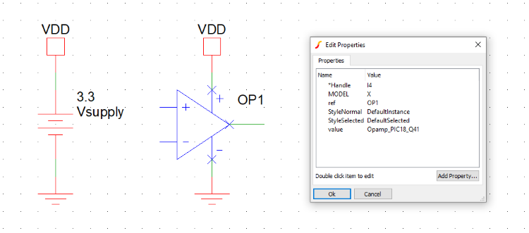
Figure 1 shows a schematic in Mindi where the PIC18-Q41 operational amplifier has been inserted along with the device properties window for that component. The PIC18-Q41 operational amplifier model requires that a positive and negative power supply be connected to the corresponding terminals to run a simulation. In this example, the power supply labeled VDD (3.3V) and the ground reference (0V) were connected to the respective nodes of the operational amplifier.
Once the main analog component of the circuit has been placed onto the schematic, the next step will be to finish drawing the circuit in Mindi by inserting the remaining parts needed to complete the design.
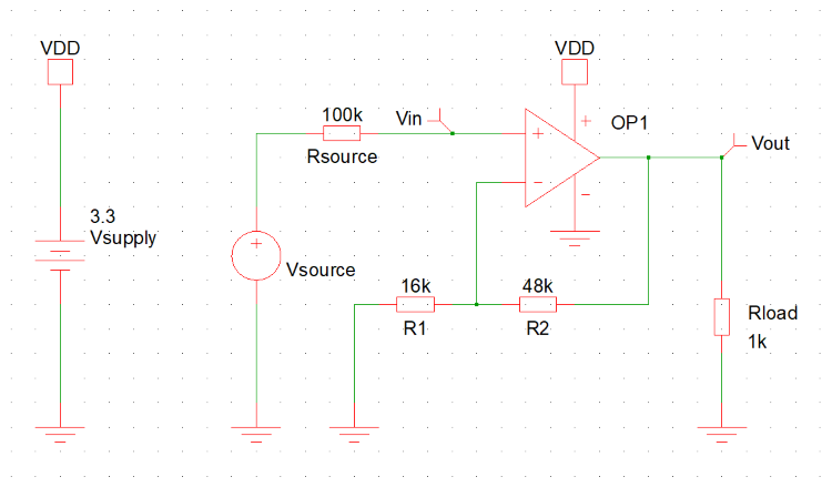
Using the PIC18-Q41 operational amplifier schematic (see example above), the next step to complete this circuit will be to place a feedback network and connect the inputs and output of the operational amplifier accordingly. In this instance, the PIC18-Q41 operational amplifier model will be used to simulate a non-inverting amplifier with a gain of 4. When all of the components have been placed and all of the connections have been made, an input source should be added to the schematic so that the circuit response can be simulated to model the application it will be used in.
There are many different voltage and current source options available in Mindi. In this example, a sinusoidal voltage source was used for simulation. Different sources can be added into a schematic by either using the quick access toolbar or by navigating to the Place tab at the top of the window and selecting from the list of available options.
In this example, the sinusoidal waveform connected to the non-inverting input of the PIC18-Q41 operational amplifier has a frequency of 50 Hz, an amplitude of 200 mV, and a positive offset of 200 mV to ensure that the sine wave generated is always larger than the ground reference. Figure 2 shows the complete schematic used in Mindi to simulate this circuit using the PIC18-Q41 operational amplifier library model.