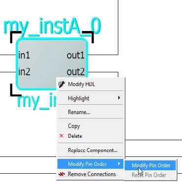
This a toggle switch. Right click an instance to open the drop-down menu. Select Modify Pin Order. A pop-up window provides instructions on how to reset pin order. The Modify Pin Order > Modify Pin Order menu provides instruction on how to modify the pin order on an instance. Press CTRL+SHIFT and click to select the pin you want to move.
Drag the mouse to a new location and release the mouse. The pin is moved to a new location. By default, input pins are on the left of the instance while output pins/inout pins are on the right. Modify Pin Order allows place the pins on any one of the four sides of the instance. A pin that has been moved away from default locations is identified by a bold arrowhead. An inward-pointing arrowhead indicates an input pin and an outward-pointing arrowhead indicates an output pin. Inout pins do not have an arrowhead when they are moved away from the default locations (right side of instance).