Another option for measuring the speed of the fan is to combine TMR0 and TMR1 to create a frequency counter. While this removes the requirement for a 16-bit divide to get the frequency, it has the problem that the resolution of the speed measurement would be very limited. When the fan is running at 14000 RPM, it only produces 56000 pulses per minute or 933 Hz. Assuming 10 measurements per second, that is only a count of 93 at maximum speed. Given the sample rate is only 10 Hz, the update rate for the PID would also be significantly limited, requiring 10s to 100s of seconds to settle in response to a change.
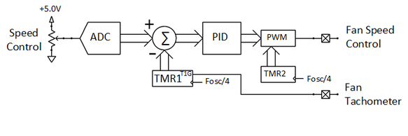
The ADC periodically measures the output voltage of the potentiometer to obtain the designed speed. The output of TMR1 is then subtracted from the ADC result to get an error value.
The error value is then loaded into the software PID controller. This software function generates a straight multiple of the error (the P component of a PID). The software also integrates the error function over multiple cycles to generate the I component of the PID. Finally, the software PID also differentiates the error function over multiple cycles to generate the D component of the PID. The three values, P, I and D, are then summed and output to the PWM.
The PWM is generated based on the output of TMR2. TMR2 runs continuously, resetting to zero when the maximum period is reached. The PWM module monitors the output of TMR2, setting the PWM output when TMR2 rolls over and then clearing the PWM output when the duty cycle register matches the TMR2 output.