This section describes the transceiver to microcontroller interface. The interface is comprised of a slave SPI and additional control signals. This interface is connected to a SAM L21 master interface as shown below. The SERCOM4 and GPIO signals dedicated to the CPU-TRX interface are not externally exposed and may not be used for any other purposes.
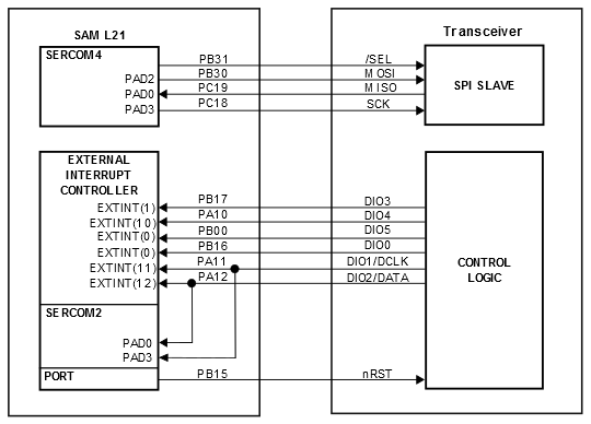
The SPI is used for register, Frame Buffer and SRAM access. The additional control signals are connected to the GPIO/IRQ interface of the microcontroller. The table below introduces the radio transceiver I/O signals and their functionalities.
|
TRX Signal |
CPU Signal Name |
Description |
|---|---|---|
|
/SEL |
PB31 |
SPI select signal, active-low |
|
MOSI |
PB30 |
SPI data (master output slave input) signal |
|
MISO |
PC19 |
SPI data (master input slave output) signal |
|
SCLK |
PC18 |
SPI clock signal |
|
nRST |
PB15 |
Transceiver Reset signal, active-low |
| DIO0 | PB16 | Digital I/O, software-configured |
| DIO1 | PA11 | Digital I/O, software-configured |
| DIO2 | PA12 | Digital I/O, software-configured |
| DIO3 | PB17 | Digital I/O, software-configured |
| DIO4 | PA10 | Digital I/O, software-configured |
| DIO5 | PB00 | Digital I/O, software-configured |