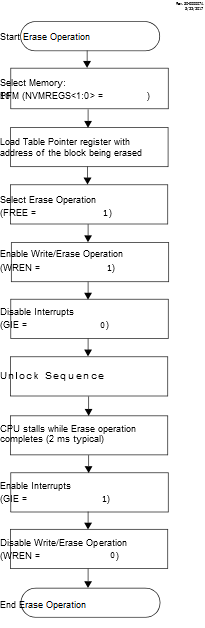
The sequence of events for erasing a block of internal program memory is:
- 1.Set the NVMREG bits to select PFM
- 2.Set the FREE and WREN bits
- 3.Perform the unlock sequence as described the NVM Unlock Sequence section
If the PFM address is write-protected, the WR bit will be cleared and the erase operation will not take place, WRERR is signaled in this scenario.
The operation erases the memory row indicated by masking the LSbs of the current TBLPTR.
While erasing PFM, CPU operation is suspended and it resumes when the operation is complete. Upon completion the WR bit is cleared in hardware, the NVMIF is set and an interrupt will occur if the NVMIE bit is also set.
Write holding register data is not affected by erase operations and WREN will remain unchanged.
Figure 1. PFM Row Erase Flowchart
Erasing a Program Flash Memory block
; This sample row erase routine assumes that the target address
; specified by CODE_ADDR_UPPER, CODE_ADDR_HIGH, and CODE_ADDR_LOW contain a
; value within the PFM address range of the device.

           MOVLW   CODE_ADDR_UPPER    ; load TBLPTR with the base
           MOVWF   TBLPTRU            ; address of the memory block
           MOVLW   CODE_ADDR_HIGH
           MOVWF   TBLPTRH
           MOVLW   CODE_ADDR_LOW
           MOVWF   TBLPTRL
ERASE_BLOCK:
           BCF     NVMCON1, NVMREG0   ; point to Program Flash Memory
           BSF     NVMCON1, NVMREG1   ; access Program Flash Memory
           BSF     NVMCON1, WREN      ; enable write to memory
           BSF     NVMCON1, FREE      ; enable block Erase operation
           BCF     INTCON, GIE        ; disable interrupts
Required   MOVLW   55h
Sequence   MOVWF   NVMCON2            ; write 55h
           MOVLW   AAh
           MOVWF   NVMCON2            ; write AAh
           BSF     NVMCON1, WR        ; start erase (CPU stalls)
           BSF     INTCON, GIE        ; re-enable interrupts
           BCF     NVMCON1, WREN      ; disable writes to memory
Important:
- 1.If a write or erase operation is terminated by an unexpected event, WRERR bit will be set which the user can check to decide whether a rewrite of the location(s) is needed.
- 2.WRERR is set if WR is written to ‘1’ while TBLPTR points to a write-protected address.
- 3.WRERR is set if WR is written to ‘1’ while TBLPTR points to an invalid address location ( Refer to the device memory map and Table 1).