The Reset Flag register (RSTCTRL.RSTFR) on the AVR will contain the reset source of the last reset. The Reset Register status LEDs display the content of the Reset Flag register inside the AVR. Reading out the reset cause makes it possible for the application code to log and report errors and unstable behavior that caused the device to be reset.
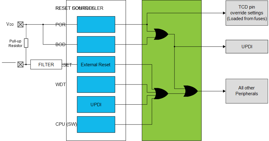
On ATtiny3217 there are six different sources that can reset the device, as shown in Figure 1.
- Power supply Reset sources:
- Brown-out Detect (BOD)
- Power-on Reset (POR)
- User Reset sources:
- External Reset Pin
- Watchdog Reset
- Software Reset
- UPDI Reset
Power-on Reset (POR)
During a power-up of a device, it is important to give the entire device a reset to put everything in a known state. It is equally important not to start executing code from Flash before the Flash and digital logic have sufficient power. When the voltage rises, the POR is activated and will hold the device in reset until the voltage is above a fixed threshold value. The POR will remain enabled as long as the device is powered.
Brown-out Detect (BOD)
The BOD monitors the power supply and compares the voltage against two threshold levels. The BOD is used on systems where the voltage should not drop below a certain level due to, e.g., the speed the device is running at or external hardware that requires a certain voltage level. If the voltage falls below the configured threshold, the BOD issues a system reset and will hold the device in reset until the voltage has risen above the threshold.
External Reset Pin
The External Reset pin is a port pin that, if enabled, will hold the device in reset when held low. The external reset will reset the entire device, except for the UPDI and TCD pin override settings.
External reset is not demonstrated on FSFEB since the UPDI and Reset shares the same pin. FSFEB uses the UPDI functionality for programming and debugging of the device.
Watchdog Reset
The Watchdog Timer (WDT) is a peripheral to help ensure correct program operation. It will recover the device from situations such as runaway or deadlocked code, by issuing a reset. When enabled, the WDT is a constantly running timer, configured to a predefined timeout period. If the WDT is not cleared within the timeout period, the WDT will issue a system reset.
Universal Program Debug Interface (UPDI) Reset
The UPDI contains a separate reset source that is used to reset the device during external programming and debugging. The reset source is accessible only from external debuggers and programmers. The UPDI reset will reset all logic except the UPDI itself, TCD pin override settings, and BOD configuration.
Software Reset
The software reset makes it possible to issue a system reset from software. The reset is generated by writing a “1” to the Software Reset Enable bit (SWRE) in the Software Reset register. The reset will take place immediately after the bit is written, and the device will be kept in reset until the reset sequence is completed. All logic is reset on software reset, with the exception of UPDI, TCD pin override settings and BOD configuration.