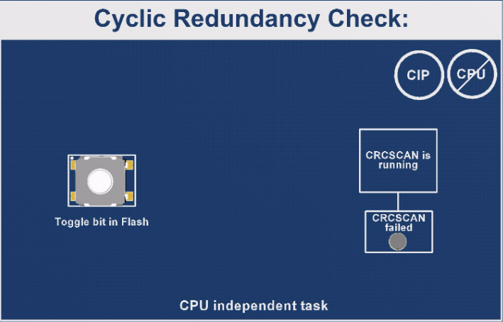
A Cyclic Redundancy Check (CRC) takes a data stream of bytes from the NVM and generates a checksum. The CRCSCAN peripheral can be used to detect errors in program memory.
The CRCSCAN peripheral expects a two byte CRC checksum to be located at the end of the area selected for scanning. For the FSFEB project, this means that a checksum has to be calculated and added to the image before it is programmed onto the device. For details on how to do this, refer to CRC Checksum Setup.
A property of the CRC module is that when a scan is started, the CRC module has priority access to the Flash. This means that the CPU is stalled until the CRC module is done. If the CRC scan passes, the OK bit in the CRC status register is set to '1'. If the scan fails, the bit is set to '0'.
In the application code, the CRC scan will be started each time the RTC gets a periodic interrupt. This happens once every second.
When the CRC scan fails, the application code will no longer clear the WDT. This means the device will be reset when the WDT times out. After the reset, the CPU will write back the correct value to the Flash address that was written to during the CRC test, to make FSFEB ready for new tests.
The CRC has the possibility to trigger a CRC interrupt when failure is detected. This feature should be selected if the user wants to make sure that the application is stopped when errors are detected in Flash. This feature is not used on FSFEB. As the CRC interrupt cannot be cleared, the device would become stuck in the interrupt handler. Due to the handling of the charlieplexed LEDs, it would become impossible to set the CRC failure LED, and FSFEB would appear to be locked.
The fact that the CRC interrupt cannot be cleared once an error has been detected is a security feature. When the CRC has detected a Flash failure, which can be anywhere in the Flash, no code is safe to execute. It is recommended to prevent the device from executing code.
The timing of the CRC operation is decided by two factors: The system clock and the size of the area to be scanned. Every third clock cycle, a 16-bit word is read from Flash, so the time it takes to scan a section of Flash can be calculated by following this formula:
- TSCAN is the time it takes to scan the area, in seconds
- BSCAN is the size of the area to scan, in bytes
- FCPU is the operating frequency of the CPU, in MHz