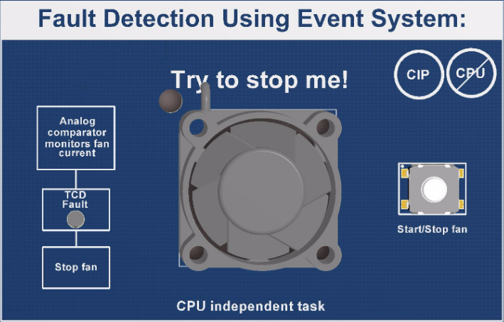
The fault detection using Event System shows how the TCD, which drives a fan, can automatically stop the fan from a fault condition. The AC and DAC monitor the current consumption of the fan. If a current consumption above the normal level is detected, which will be considered as a fault condition, a signal is sent to the TCD. The signal is sent using the Event System, which is CPU independent. The TCD automatically stops the fan upon receiving the event.
The fan motor on FSFEB is driven by the TCD. Since this is not a motor control demonstration, but rather a demonstration of fault detection and automatic shutdown, the motor control part is done in a very simple way. Ideally, a stable DC voltage from TCD would be best to power the fan motor since it already has a speed controller onboard. However, as the TCD cannot provide this, the signal will be PWM with a very short low period.
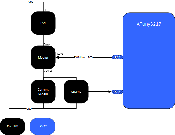
To be able to measure the fans current consumption, a small resistor is needed in series with the fan motor and ground. The voltage drop over the resistor will be amplified through a simple op-amp circuit and connected to the positive input on AC. The measurement technique is called low-side current sensing. It is shown in Figure 2.
The internal DAC is connected to the negative input on the AC and is used to set the trigger level for the AC. The AC output is further connected to TCD0 input A through the event system. When the fan is started the current consumption is measured through the series resistor and the voltage drop is amplified through the op-amp. If the current consumption is lower than the level set by the DAC, the AC output will be low. As soon as the fan is loaded the current consumption will increase above the set DAC level and the AC output will become high. This will create an event to the TCD. The TCD will then stop driving the fan and wait until the user restarts the fan.
The current consumption is at its highest when the fan is started and decreases as the fan speed increases. To avoid start-up current from triggering the AC the TCB1 timer interrupt is used to gradually decrease the DAC value the first second after the button is pressed down. The first time the TCB1 interrupt triggers the DAC value is set high, and the TCD0 timer is started.
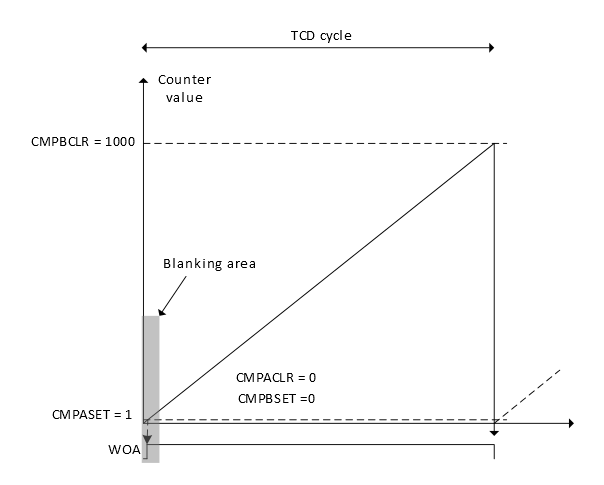
Sometimes, when the TCD PWM output signal goes from low to high, a spike in current generated by the motor inductance might falsely trigger the AC to generate an event that stops the timer. To avoid this, the timer is configured to use the input blanking functionality. The timer can be set up to mask out the inputs for a programmable time in the selected TCD cycle. This means that the timer will ignore any event if it happens within this time period.
When the fault detection is triggered, the TCD fault LED will be turned ON and the application heartbeat frequency is increased to signal to the user that something is wrong. If the Start/Stop button is not pressed within 3 seconds, the application code will execute a software reset to reset the device.