Follow these instructions to set up and configure the module as a GAP-Central and
GAP-Peripheral device.
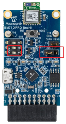
- 1.Connect the BM70/71 XPro directly to the PC using the Micro USB on the board. The BM70/71 XPro board must enumerate a COM port. If not, check the PC for the necessary MCP2200 drivers.
- 2.Set up the module to Programming
mode by configuring the switch 1 and 2 in the 3-pin DIP switch to the ON state
as illustrated in the following figure. The switch 1 sets the mode of operation
on the module (between Application mode and Flash Write mode) and switch 2
enables the blue LED. For more information on the DIP switch, refer to the pin
P2_0 in the BM70/71 Bluetooth® Low Energy (BLE) Module Data Sheet
(DS60001372). The blue LED (labeled BT_ACT, LD4) must be solid blue now. If
not, press the Reset button on the board. Note: Ensure the jumper on J2 is set to USB as illustrated in the following figure.Figure 1. Figure 2-1. BM70/71 XPro Board
- 3.Ensure that the BM70/71 module
has the correct BM70/71 firmware installed. However, if the RN4871
firmware is programmed into the module earlier, reflash the BM70/71 firmware
using the following steps:
- a.Open the Flash Update
Tool (inside the Firmware and Software Tools file) available as part of
Firmware & Software Tools Package. Set the parameters in the tool under the Software
section, and click Connect.Figure 2. Flash Update Tool
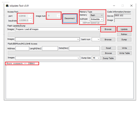
- b.The COM port connection
confirmation displays in the console available inside the tool.
Port connect -> comXappears on the console upon successful connection with the device. If not, check if the COM port is connected through any other PC tool, and check the instructions provided in step 2. - c.Select all the Firmware
files available as part of the Firmware & Software Tools Package (
FirmwareUpdateTool-->Firmware
                                folder
). Use the browse option inside the Firmware Update Tool, and click Update.Figure 3. Selection from Flash Update Tool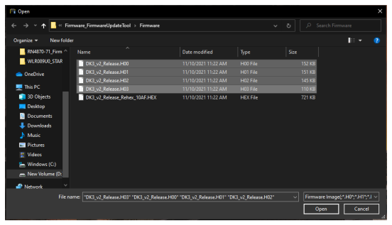
- d.
Notes:
- By Default, the BM70/71 module has proper firmware flashed.
- If the BM70/71 module has RN4871 firmware flashed earlier, the module does not operate as expected, and the Studio project fails.
- a.Open the Flash Update
Tool (inside the Firmware and Software Tools file) available as part of
Firmware & Software Tools Package. Set the parameters in the tool under the Software
section, and click Connect.
- 4.Open the UI tool (inside the Configuration Tool folder) for the BM70/71 module available as part of Firmware and Software Tool Package. Choose the latest version (BM70/71).
- 5.Select the default configuration text file (inside the Configuration Tool file) available as part of the downloaded package specific to the BM70/71 module.
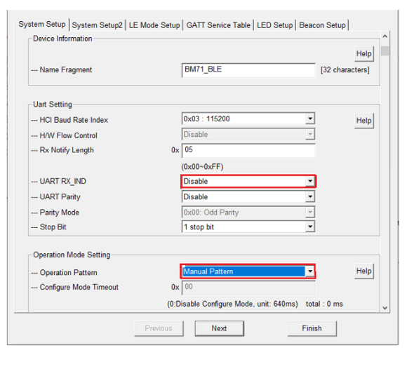
- 6.Configure the BM70/71 XPRO board
by making a modification to the configuration file as illustrated in the
following figure, and flash the modified changes to the BM70/71 XPRO board. The
configuration changes demand the module to configure in Manual mode.Note: By default, the BM71 XPro board is configured to operate in Auto mode. The Microchip Studio project, however, requires the module to be set up in Manual mode.Figure 4. Configuration Tool
Note: The instructions provided until step 6
are common for GAP-Central and GAP-Peripheral device setup.