This section provides the instructions to flash the configuration file into the BM70/71
device using the UI tool.
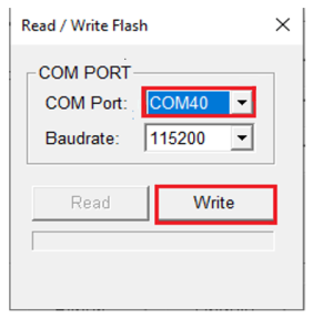
- 1.In the UI tool, select the COM
port corresponding to the BM70/71 XPRO board. Ensure the blue LED is still solid
ON. This is to ensure that the module is in Write Flash mode. Click Write as illustrated in the following figure.Figure 1. UI Tool
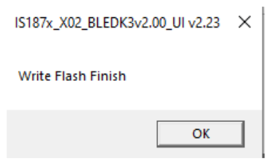
- 2.After the confirmation
acceptance, the configuration file is written into the device memory, and the
confirmation dialogue box appears.Figure 2. Confirmation Dialog Box
- 3.Now that the Flash Write operation is completed, set the Switch 1 in the DIP switch to OFF (Application mode), and change the Jumper J2 to EXT1 to enable the interfacing with the host controller board.