Todo: Create a
new Atmel | START Project, where CLOCK, ADC, and USART modules are
configured.
- 1.Open Atmel Studio 7.
- 2.Create a new Atmel | START project in Atmel Studio by
- 2.1.Open the CREATE NEW PROJECT window by selecting File->New->Atmel START project.
- 2.2.Select the target hardware by entering 817X in the Filter on device... text box and selecting ATtiny817 Xplained Pro from the list.
- 2.3.Create the project by clicking CREATE NEW PROJECT as shown in Figure 1.
Figure 1. CREATE NEW PROJECT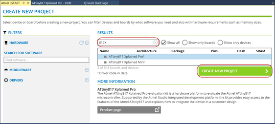 Info: The MY SOFTWARE COMPONENTS window should appear.
 - 3.Rename the project by clicking MY
PROJECT in the MY SOFTWARE COMPONENTS window and select Rename
Component as shown in Figure 2. Figure 2. Rename Component
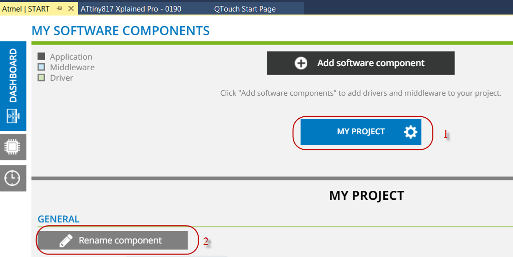 Info: The RENAME COMPONENT window should appear.Enter the project name, for example, ADC_Training, in the popped up RENAME COMPONENT window and click Rename to close it.Note: This step is optional to rename the project name.
 - 4.Add ADC and USART drivers to the project
by
- 4.1.Open the ADD SOFTWARE
COMPONENTS window by clicking

- 4.2.Expand Drivers by clicking +
- 4.3.Select ADC and USART by clicking
 , as shown in Figure 3Info: ADC and USART will be highlighted as the selected modules as shown in Figure 3.Figure 3. Add RTC and USART Modules
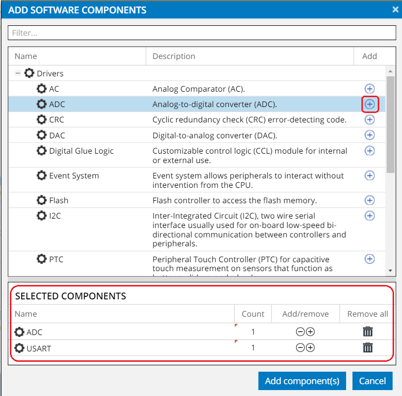
- 4.4.Add the drivers to the project by clicking the Add component(s) button.
- 4.1.Open the ADD SOFTWARE
COMPONENTS window by clicking
- 5.Open the CLOCK CONFIGURATOR window
by clicking
 on the navigation tab at the left side of the window as shown in Figure 4.Figure 4. Clock Configuration
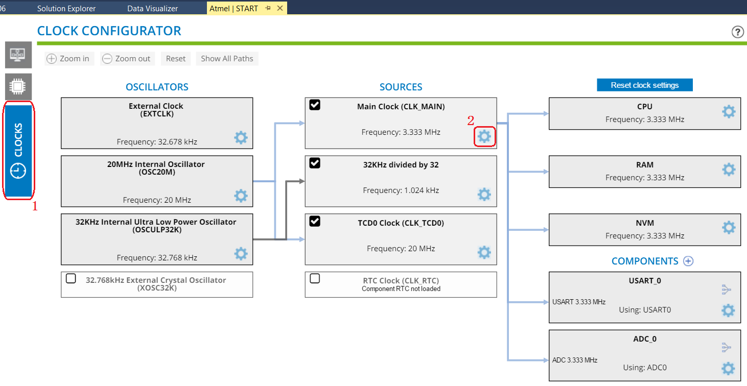 Info: The CLOCK CONFIGURATOR window consists of oscillators and clock sources of different types. Required clock source can be selected and the calculated output frequency will be displayed.
- The OSCILLATORS
section displays the oscillators available for the selected device. The
oscillator parameters can be configured by clicking
 to
select Settings Dialog.
to
select Settings Dialog. - The SOURCES section is used to configure clock frequency by selecting input signal and prescaler settings.
- The OSCILLATORS
section displays the oscillators available for the selected device. The
oscillator parameters can be configured by clicking
- 6.Configure the Main Clock (CLK_MAIN) clock
source by
- 6.1.Open the CLOCK SETTINGS window by clicking as shown
in Figure 4.
- 6.2.Select 20 MHz as the Main Clock Source from the drop-down menu.
- 6.3.Select 4 as the Prescaler division from the drop-down menu.
- 6.4.Close CLOCK SETTINGS by
clicking the Close button.Figure 5. Clock Settings
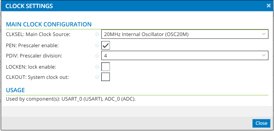 Info: For this application, 20 MHz OSC is chosen as the main clock source with prescaler division equal to 4. The resulting CPU clock frequency is 5 MHz.
For quick reference, clicking
 next to
each configuration will provide the data sheet description of individual bit
settings.
next to
each configuration will provide the data sheet description of individual bit
settings.
- 6.1.Open the CLOCK SETTINGS window by clicking
- 7.Return to MY SOFTWARE COMPONENTS,
by clicking
 in the navigation tab on the top of the left side of the window.
 - 8.Configure the ADC module by following the steps in Figure 6:Figure 6. ADC Configuration
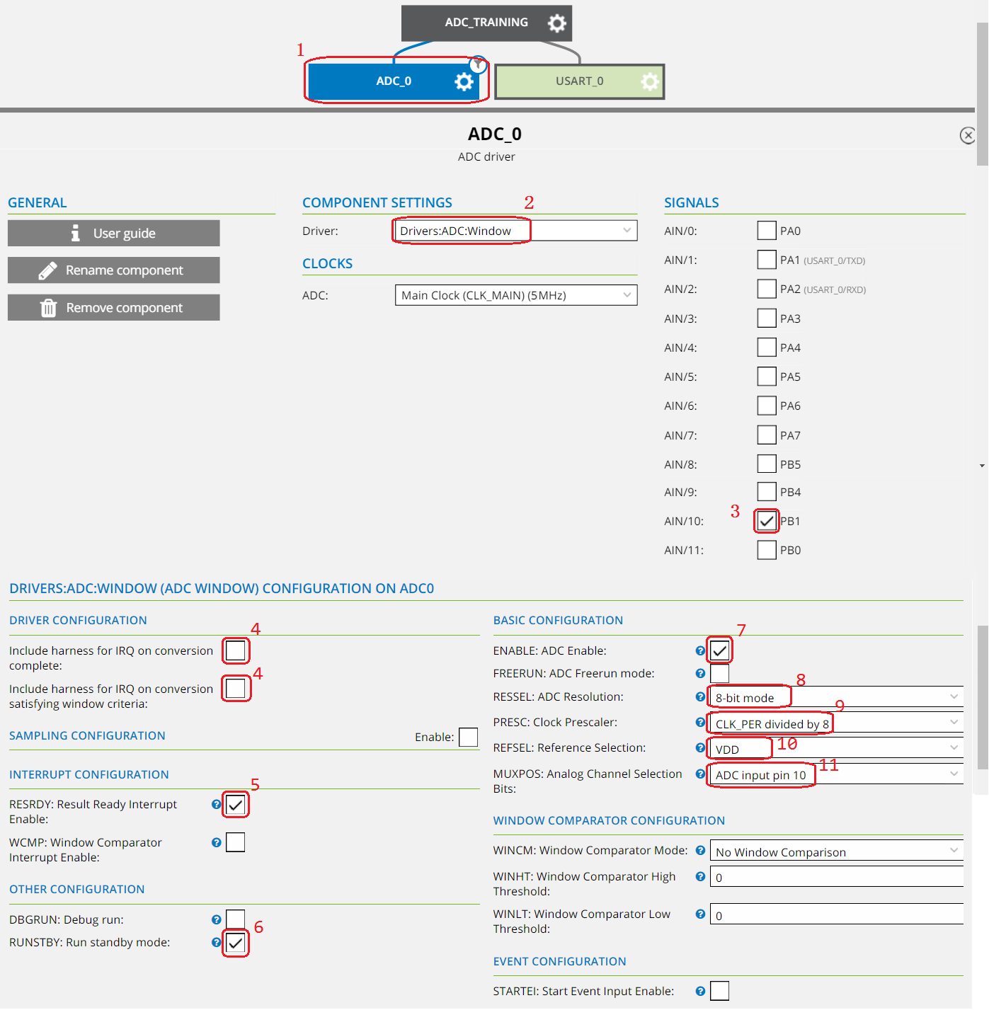
- 8.1.Open the configuration menu for ADC, by clicking ADC_0.
- 8.2.Select Drivers:ADC:Window as Driver from the drop-down menu.
- 8.3.Select PB1 as analog input AIN/10 from the SIGNALS menu.
- 8.4.Ensure all interrupt handlers end up in driver_isr.c for this training, by un-checking Include harness for IRQ on conversion...
- 8.5.Enable the Result Ready Interrupt, by selecting the RESRDY:Result Ready Interrupt Enable checkbox.
- 8.6.Ensure the ADC runs when the device is in Standby Sleep mode, which will be used in the next assignment.
- 8.7.Ensure the ADC is enabled after initialization, by selecting ENABLE:ADC Enable.
- 8.8.Select 8-bit mode as the RESSEL:ADC Resolution.
- 8.9.Configure the ADC clock to 625 KHz, by selecting CLK_PER dividend by 8 from the PRESC:Clock Prescaler drop-down menu. The main clock runs at 5 MHz, which gives ADC clock at 625 KHz.
- 8.10.Select VDD as Reference Selection from the drop-down menu.
- 8.11.Select ADC input pin 10 in the MUXPOS: Analog Channel Selection Bits field to select the analog input AIN/10 connected to the ADC.
- 9.Configure the USART module by following
the steps in Figure 7: Figure 7. USART Configuration
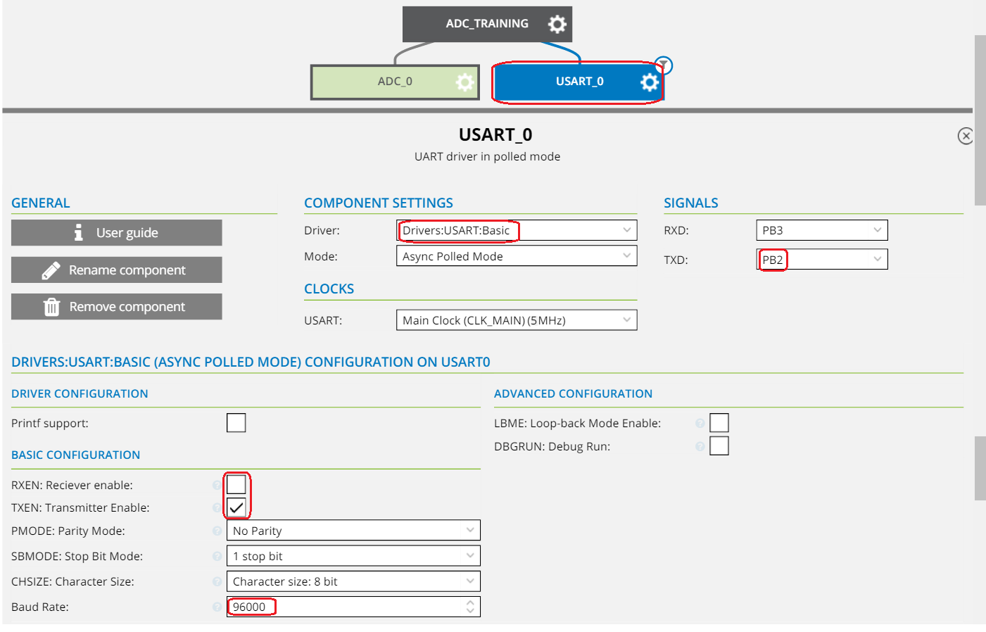
- 9.1.Open the USART configuration menu, by clicking USART_0.
- 9.2.Select Driver:USART:Basic as Driver from the drop-down menu.
- 9.3.Select PB2 as the USART output by selecting it from the TXD drop-down menu.
- 9.4.Ensure the output is enabled upon
initialization, by selecting TXEN:Transmitter Enable.Info: The device will only send data over USART, so the RXEN:Receiver Enable can remain unchecked.
- 9.5.Configure a high baud rate in order
to ensure fast USART data transfer, by setting the Baud Rate to
96000.Info: Transferring the USART data fast will enable the device to spend more time in Sleep mode, which will reduce the current consumption. The Sleep mode will be used in the following assignment.
- 10.Generate the project by clicking
 .
. - 11.Select the desired path where the project
should be stored as shown in Figure 8 as an example and click OK.Figure 8. New Atmel Start Project
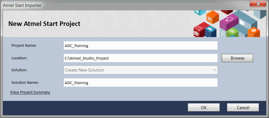
Result: An Atmel | START project, featuring an ADC and USART driver, has been created in
Atmel Studio.