The device has been programmed to start ADC conversion when RTC interrupt is triggered. When one ADC conversion is completed, the ADC result will be printed to the USART terminal. The power consumption on the device can be observed in embedded power debugger in Data Visualizer.
Todo: Observe ADC
functionality and power consumption in Data Visualizer.
Click the Data Visualizer tab to observe the ADC functionality and power
consumption, as shown in Figure 1.
Figure 1. ADC Data Print to USART Terminal and
Power Analysis
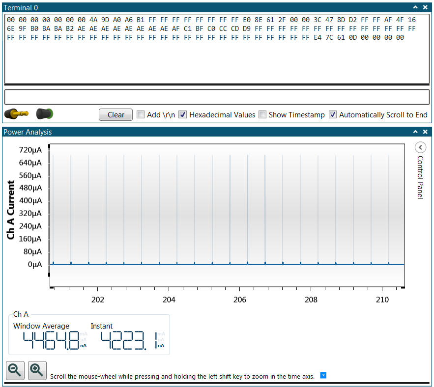
The ADC result is printed as shown in the terminal, in the same manner as in the
previous assignment. When rotating the potmeter knob, the print ADC result changes
accordingly.
Result: By rotating the potentiometer knob, the
voltage input to ADC input pin, PB1, is changing. This can be observed as the ADC result
being sent to the terminal window is changing as one rotates the knob.
When looking at the current consumption in the power analysis window, the average current is about 4.5 μA. This is a significant reduction from the 2.8 mA current consumption in the previous assignment. The high peak glitches are about 690 μA, which refers to the case when doing the ADC conversion and USART transmission to the terminal. This scenario consumes most power but is still a significant drop from 2.8 mA.
Result: When using
the RTC overflow interrupt and Standby Sleep mode, the average current consumption can be
reduced from 2.8 mA from previous assignment down to the 4.5 μA. The peak glitches when doing
the ADC conversion and USART transmission has also been reduced from 2.8 mA to 690 μA.