Once the application code development is completed it is time to connect the potentiometer to the ADC input pin available on ATtiny817 Xplained Pro and program the device on ATtiny817 Xplained Pro.
Todo:
- Connect the potentiometer to the ADC input pin on ATtiny817 Xplained Pro
- Connect ATtiny817 Xplained Pro to Atmel Studio
- Program the device on ATtiny817 Xplained Pro
- 1.Connect the potentiometer to the breadboard. Notice how the pins correspond to the letters/numbers on the breadboard.
- 2.Connect the pins on the potentiometer to
the extension header of ATtiny817 Xplained Pro, as shown in Figure 1.
- 2.1.Potmeter pin 1: Connect to the GND pin on the kit.
- 2.2.Potmeter pin 2: Connect to the PB1 pin on the kit.
- 2.3.Potmeter pin 3: Connect to the VCC pin on the kit.
Figure 1. Connect Potentiometer to the ATtiny817 Xplained Pro Kit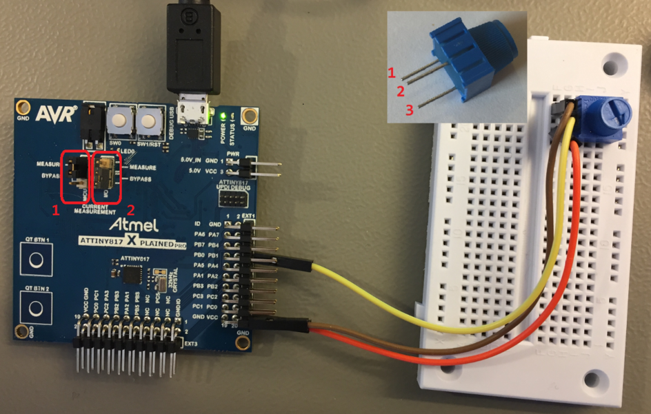 Info: A potentiometer, also called a potmeter, is a three-terminal resistor with a sliding or rotating contact that provides an adjustable voltage divider.
 - 3.Enable current measurement of the device by placing the jumper on MEASURE for MCU, as shown in Figure 1.
- 4.Disable current measurement of the I/O pins by placing the jumper on BYPASS for I/O, as shown in Figure 1.
- 5.Connect ATtiny817 Xplained Pro to the computer by using a Micro-USB cable, as shown in Figure 1.Info: The ATtiny817 screen shows up.
- 6.Program the device on ATtiny817 Xplained Pro by
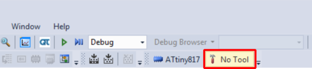
- 6.1.Open the Tool pane in project
properties by clicking No Tool, as shown in Figure 2.Figure 2. Tool Button
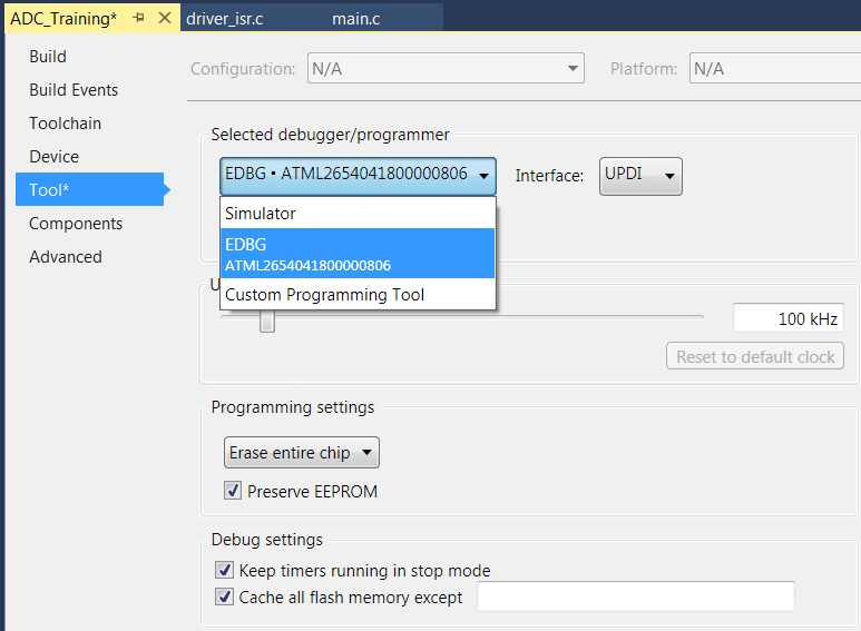
- 6.2.Choose EDBG as the Selected
debugger/programmer as shown in Figure 3.Figure 3. Debugger Selection
- 6.3.Program the device by clicking
Debug->Start Without Debugging or by using the shortcut
Ctrl+Alt+F5.Info: Start Without Debugging will build the project and program the device as long as there are no build errors.Tip: The device can also be programmed by using the Device Programming menu, by clicking Tools → Device Programming.
- 6.1.Open the Tool pane in project
properties by clicking No Tool, as shown in Figure 2.
Result: Hardware
setup is completed and the application code is running on ATtiny817 Xplained Pro.