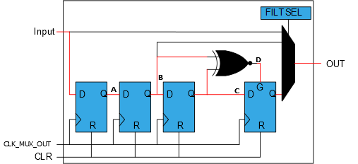
To be sure to remove all glitches, the filter options may be selected if the user wants to avoid spikes and glitches that affect the system. The filter will first run the signal through the two-stage synchronizer and then further through the filter.
0’.- If the two XNOR inputs are equal,
its output is ‘
1’ - If the XNOR output is
‘
1’, the gate input on the last D flip-flop is high - If the XNOR output is
‘
0’, the gate input on the last D flip-flop is low
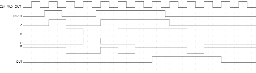
Sometimes, based on the logic values used as inputs to the LUT, a valid output signal can be high for a few clock cycles. If the filter option is chosen in such cases, it will break the function of the system by filtering out valid signals. The filter may only be used when it does not matter if the signal is delayed or shortened by the filter. Before implementing any of the filter options, it would be recommended to analyze what is the shortest valid signal out of the LUT in the current configuration. If the shortest signal is shorter than two cycles, a filter must not be used.