At the start of the bootloader application, a physical pin state can be used to determine if the MCU will enter Bootloader mode or start the user’s application. If this boot pin is high, BOOTRP is enabled and the execution jumps to APPCODE, otherwise the bootloader starts and waits to receive data from UART.
When entering Bootloader mode, the on-board LED is turned on, and it is toggled when a page boundary is reached.
After starting, the bootloader waits for an additional tag
(“INFO”) to be received via the communication interface, followed
by 124 bytes of data. This 128-bytes buffer contains information about the application
image that will be transferred. The used structure for the information buffer is the
following:
typedef struct
{
	uint32_t start_mark;
	uint32_t start_address;
	uint32_t memory_size;
	uint8_t  reserved[116];
}application_code_info;
The wait_mark contains the “INFO” tag; the
start_address contains the user application start address; the
memory_size contains the image size (number of bytes). The next 116
bytes are reserved for future improvements.
After receiving image information, an additional tag
(“STX0”) is expected at the end of the information buffer, then the
bootloader will start writing data to the APPCODE section.
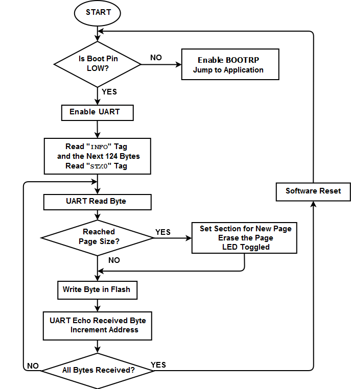
The bootloader expects that the application code is received byte-by-byte in incremental order of Flash address. When a new page boundary is reached, this is first erased and prepared for the next writes. When the number of bytes indicated in the image information buffer is reached, the bootloader will execute a software Reset and will start the new application.
The following image shows the flow diagram of the bootloader operation: