The ATA8510/15 integrates a transmitter that is capable of sending data with various options:
- Frequency bands: 310-318 MHz, 418-477 MHz and 836-956 MHz
- Data rates up to 80 kBit/s Manchester coding or 120 Ksym/s Non-return-to-zero (NRZ) coding in Buffered and Transparent mode
- ASK or FSK modulation
- Transparent or Buffered mode
- ASK shaping filter
- Gauss-shaping digital filter
This section describes the hardware blocks that are integrated to perform the transmit functionality. For detailed information on system and software flows, refer to the ATA8510/15 Industrial User's Guide (DS50003142).
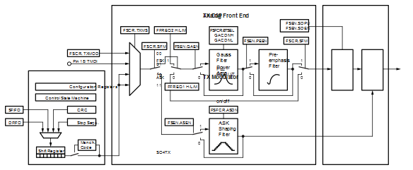
The user can select the transmission data source from a register bit. The transparent input pin 18 (TMDI) and the TX modulator fetches the data from the DFIFO and SFIFO.
If ASK/On Off Keying (OOK) modulation is selected, use the data stream to directly switch the power amplifier ON and OFF. The transmitted carrier frequency is set by the PLL frequency synthesizer.
If FSK modulation is selected, use the data stream to switch between two frequencies that are generated by the PLL frequency synthesizer. The power amplifier is constantly on. Use the power ramping (ASK shaping) during ON and OFF switching. To reduce the occupied bandwidth, enable the digital Gauss-shaping filter. For data rates above 20 kHz Manchester or 40 kHz NRZ-coding, enable the digital preemphasis filter to compensate for the Phase Locked Loop (PLL) loop filter.