To quickly get started performing calibration on a supported device, follow these steps:
- 1.Download and install Atmel Studio 7.0 (or later) from http://www.atmel.com.
- 2.Download and unzip the code for this application note, AVR053 (any location can be used, here called \AVR053).
- 3.Open the rc_calib.atsln project/solution in Atmel Studio.
- 4.Select the target device in Atmel Studio (the default device is ATmega168PB). Many, but not all, tinyAVR and megaAVR devices are supported.
- 5.Click on the RC_Calibration.asm icon to open the file.
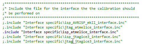
- 6.Select the desired interface by removing
the semicolon from one of the include lines in RC_Calibration.asm as shown in the
figure below.Figure 1. Selecting the Interface in RC_Calibration.asm
- 7.Measure the frequency of the calibration clock with a frequency counter or an
oscilloscope.
- 7.1.The calibration clock is generated on the MOSI pin on an ISP tool or the TDI pin on a JTAG tool.
- 7.2.To obtain this signal on the tool,
connect the tool to a PC and open a command shell window (a DOS prompt) and
navigate to the directory C:\Program Files
(x86)\Atmel\Studio\7.0\atbackend. Note that the exact path to the
atbackend directory may vary slightly from this depending on the
versions of Atmel Studio and Windows® and how Atmel Studio
was installed. Type in “atprogram –t <toolname> -d <devicename>
calibrate”, and press enter. An example command line is shown in the figure below.
This will cause the calibration clock to be generated for a few seconds.Figure 2. Command to Obtain Calibration Clock on the Tool
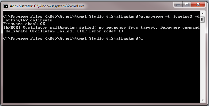
- 7.3.The error “no response from target” may occur, but it is OK in this case because the purpose of the command is to force the tool to generate the calibration clock so it can be measured accurately.
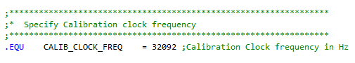
- 8.Change the line in the interface
specific file “.EQU CALIB_CLOCK_FREQ = XXXX” to reflect the measured frequency in Hz. An
example is shown in the figure below for the measured frequency of 32092Hz.Figure 3. Updating Calibration Clock Frequency
- 9.In the RC_Calibration.asm file,
specify the desired target frequency (.EQU TARGET_FREQ = XXXX) and the desired accuracy
(.EQU ACCURACY = XX).Note: If the accuracy is too tight it may not be possible to calibrate the device and the calibration will fail. Refer to the device data sheet for achievable accuracy.
- 10.Save all modified files in Atmel Studio by clicking on "File" then "Save All".
- 11.Click on "Build" then "Build rc_calib" to assemble the project and generate the hex file that should be programmed into the device.
- 12.Exit Atmel Studio.
- 13.Using any text editor, open the batch file corresponding to the chosen programming tool and interface.
- 14.Edit the file to match the desired device, by modifying the "@SET CPU=xxxx" line, for example "@SET CPU=atmega168pb".
- 15.If the JTAG interface is going to be used for calibration, note that the reset line must be available for the Atmel-ICE, JTAGICE3, or JTAGICE mkII.
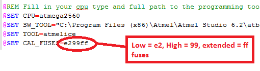
- 16.Edit the fuse settings to the desired
settings for the device as shown in the figure below by modifying the argument to
CAL_FUSES. Make sure that the settings correspond with the desired calibration
frequency: select 8MHz internal RC if calibrating the device to 8MHz. Verify that the
"Watchdog Timer always on" fuse is not set.Figure 4. Fuse Settings
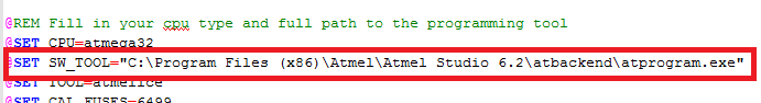
- 17.If the install path for Atmel Studio
differs from the one used in the batch file, change the path to the relevant
atprogram.exe file as shown in the figure below.Figure 5. Tool Path
- 18.For production calibration the @PAUSE command at successful calibration can be removed.
- 19.Save the batch file.
- 20.Connect the tool to the target board. Power the target board and tool. Verify that the serial or USB cable is attached between the tool and the PC.
- 21.Open a command shell window (a DOS prompt), navigate to the directory “rc_calib\Batch file\”, and execute the appropriate batch file (atprogram_ATMELICE_ISP_rc_calib.bat, atprogram_JTAGICE3_ISP_rc_calib.bat, etc.).
- 22.Wait several seconds for the calibration to complete. The batch file can also be modified to program custom firmware rather than the calib_test.hex firmware after the calibration. Be aware that the new calibration value should be loaded into the OSCCAL register at run-time by the firmware.