The application note describes the implementation of a TWI slave. The driver is written as a standalone driver that can easily be included into the main application. Use the code as an example, or customize it for own use. Defines and status registers are all set in the application note header file.
The core of the driver is interrupt driven and therefore “runs in parallel” to the other processes in the application. After initializing the driver, all communication with the driver is made through a global status register variable, and the transmit and receive buffers. The size of the communication buffers can be changed in the driver header file.
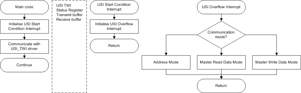
The main code communicates with the drivers through registers and buffers.
The driver takes care of the low level communication as transmission/reception of address, data, and ACK/NACK. High level operations like address setting, message interpreting, and data preparation, must be taken care of by the main application.
When a START condition is detected the USI Start Condition Interrupt sets up the USI Overflow Interrupt to start receiving the first package. The USI Overflow interrupt is always set to trigger after sampling eight bits. This way the CPU is free to operate on other application specific operations during the bit sampling/transmission.
Since the USI Start Condition and USI Overflow event holds the SCL line when activated, it is not timing critical when the interrupts are to be executed. If other operations are preventing the interrupts to execute, then proper operation will still be ensured by the driver. However, to keep the communication speed on the TWI lines as high as possible the SCL time should be released a quickly as possible.
Detection of the START Condition event is always enabled. So during any state of the communication sequence, the driver will reset the reception if a USI Start Condition is detected.
Any TWI message has according to the standard, an undefined length. The data to be transmitted/received needs to be held in buffers. The buffers contain all data bytes within one single message. The buffers must be read/rewritten before next the transmission.
TWI address administration must be controlled from the application itself. The USI_TWI_Slave_Initialize function takes the new address as a parameter and stores it for the driver to verify on each message reception. Return the initialize function to reset the address.
There are six different states gathered in three “main” states the communication can be in when entering the USI Overflow Interrupt. They are “Address Mode”, “Master Read Data Mode”, and “Master Write Data Mode”. The states are controlled internally with the USI_TWI_state variable.