This peripheral works by incrementing a 20-bit accumulator register by the value of the increment register on every pulse of the input clock. Every time the accumulator register overflows, an output pulse is generated.
Three NCOs are used in this application: a master NCO and two slave NCOs, one for each axis. Each slave NCO toggles the step pin of the stepper drivers for the corresponding axis to produce movement. By configuring a master NCO, such that its output frequency corresponds with the desired overall speed of movement, the two slave NCOs can be configured to produce the correct proportional speed.
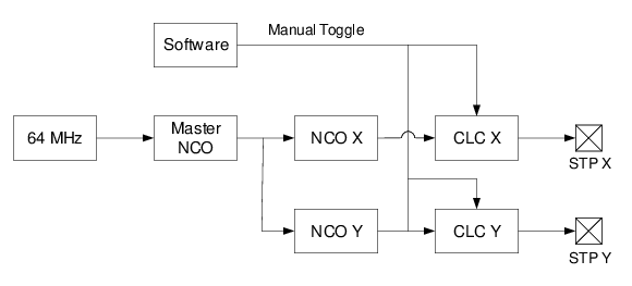
The block diagram of the NCOs necessary for a two-axis system can be seen in Figure 3-1. The master NCO provides the desired speed while two slave NCOs reduce that to the speed required in each axis. The two output frequencies are then sent to Configurable Logic Cells (CLCs) that drive the X and Y step pins, as described in the Stepper Motors section.
CLCs are a highly flexible peripheral that allow for logic such as AND and OR gates to be applied to a wide variety of inputs. In this case, the CLCs are configured to pass the output of the corresponding NCO, with the Output Polarity bit of the CLCnPOL register used to allow the pin to be toggled by software, if needed. This is necessary in the homing process described in the Home section.