Since the speeds of the two axes are proportional to the frequency of the master NCO, a change to the frequency of the master NCO results in proportional changes to the frequencies of the two slave NCOs. This means that increasing the master NCO increment value will increase the speed of both axes while decreasing it will decrease the speed of both axes, all without the need for additional calculations.
Some of the newer PIC18 microcontrollers have the Direct Memory Access (DMA). This module helps transfer chunks of data between different memory locations without any CPU intervention. By using the DMA, this acceleration can occur without the need for the processor to copy new values into the increment register. The DMA can, when triggered, copy data from one memory location to another.
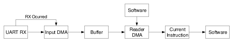
The layout of the two DMA modules used for this application is shown in Figure 3-2. The primary DMA module feeds values from a LUT of increment values to the increment register of the NCO, which changes the speed of movement proportionally. A timer, fed by the output of the NCO, is configured to control the rate of acceleration by causing the DMA to change the increment value at set intervals.
Since the input frequency of the timer is the frequency of the NCO (as the speed is increased), the update rate from the LUT also increases. To help compensate for this, a second DMA module is used, which feeds timer period values from a LUT into the period register of the timer. By increasing the period as the frequency increases, the actual time between NCO increment increases (in terms of actual seconds) can be kept constant. This prevents any need for a higher number of samples at the faster end to compensate.
This method of acceleration requires very little work on the part of the processor, outside of initial configuration. To achieve a target speed, the DMA 'n' Source Size (DMAnSSZ) register (the number of bytes of the source data) is set to the acceleration step of the desired speed for the two DMA modules.
DMA Ramp Up Configuration
// Source starts at location of NCO lookup table
DMAnSSA = NCO_INC_LUT_LOC;
// Destination starts at location of NCO Increment Address
DMAnDSA = NCO_INC_LOC;

// Increment source/destination location each time
DMAnCON1bits.DMODE = INCREMENT_POINTER;
DMAnCON1bits.SMODE = INCREMENT_POINTER;

// Copy bytes from source until desired location is reached
DMAnSSZ = desired_lut_index * NCO_INC_SIZE;
The DMA will continue transferring data until the target speed has been reached. At this point, the DMA Source Interrupt (DMAxSCTIF) will fire, indicating that acceleration is complete.
To slow down the machine at the end of travel, DMA 'n' Source Start (DMAnSSA) register (the address to start copying at) is set to the end of the location in the LUT associated with the current speed. As DMAnSSZ remains the same, the DMA is set to decrease the memory pointer copying from each transaction, rather than increment.
DMA Ramp Down Configuration
// First byte in LUT
void * start_of_lut = NCO_INC_LUT_LOC;
// Location to start reversing from
void * location_to_copy = start_of_lut + source_size - 1;
DMAnSSA = location_to_copy;

// Start/End of NCO Inc Register
void * start_of_nco_inc = NCO_INC_LOC;
void * end_of_nco_inc = start_of_nco_inc + NCO_INC_SIZE - 1;

// Number of bytes to return to start
uint16_t source_size = current_lut_index * NCO_INC_SIZE;

// Start copying to end of location (backwards)
DMAnDSA = end_of_nco_inc;
// Copy until it gets back to start
DMAnSSZ = source_size;

// Decrement source/destination each time
DMAnCON1bits.DMODE = DECREMENT_POINTER;
DMAnCON1bits.SMODE = DECREMENT_POINTER;