The microcontroller's (MCU’s) OPAMP peripheral can be configured to linearly amplify millivolt-level signals. This capability can be used to greatly simplify the hardware interface with an electret microphone.
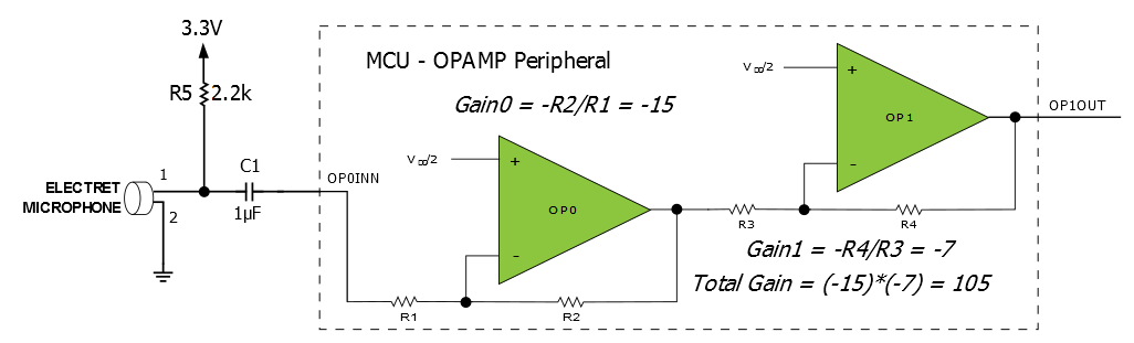
The schematic diagram of the electret microphone interface with the MCU is shown in the figure above. Only two components are required in addition to the microphone and MCU: Resistor R5 for biasing the microphone, and capacitor C1 for blocking the DC voltage and allowing the audio signal to pass through. The remainder of the amplification circuit is provided by the OPAMP peripheral inside the MCU.
As shown in the schematic diagram, op amps OP0 and OP1 inside the MCU’s OPAMP peripheral are configured as cascaded inverting amplifiers, using resistors that are also inside the OPAMP peripheral. The gain of the OP0 stage is determined by the ratio -R2/R1, and the gain of the OP1 stage is determined by the ratio -R4/R3. In the schematic, the first stage is shown with a gain of -15 and the second stage is shown with a gain of -7 for an overall gain of 105. Because the resistor ratios can be changed under firmware control, it is possible for the MCU to adjust the gain if needed. For example, in a high-noise environment, a gain of 105 might be too large, causing the output signal to saturate and distort. In this case, the gain of one or both op amps could be reduced as needed.
Depending on the requirements of the application, output pin OP1OUT can be connected via a circuit board trace to external circuitry, or it can be used as either an analog comparator input or an analog-to-digital converter (ADC) input on the same pin of the MCU.